 |
ar8wzn00000552
INPUT/OUTPUT CHECK MODE OPERATION
id092200100900
Operation procedure
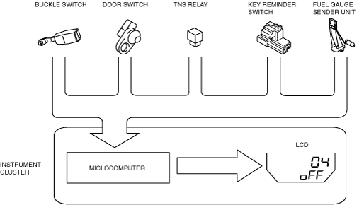
Input circuit check
|
Check code |
Parts sending input signal |
|---|---|
|
01
|
Buckle switch
|
|
04
|
Door switch
|
|
08
|
TNS relay
|
|
22
|
Fuel gauge sender unit
|
|
31
|
Key reminder switch
|
|
55
|
Dimmer switch
|
ar8wzn00000552
|
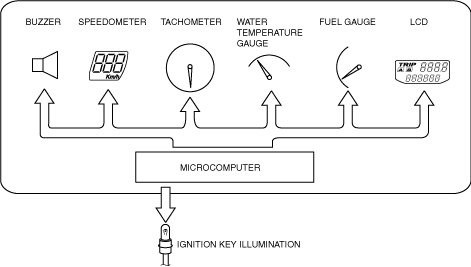
Individual circuit check
|
Check code |
Parts sending input signal |
|---|---|
|
12
|
Speedometer
|
|
13
|
Tachometer
|
|
14
|
Buzzer
|
|
16
|
Fuel-level warning light
|
|
18
|
Ignition key illumination
|
|
23
|
Fuel gauge
|
|
25
|
Water temperature gauge
|
|
26
|
LCD
|
ar8wzn00000557
|
PID/Data Monitor and Record
|
Monitor item |
Input-output signal/part name |
Unit/State |
Terminal |
|---|---|---|---|
|
CCNT_HE
|
DTC
|
Number of continuous DTCs
|
—
|
|
ECT_GAUGE
|
Water temperature gauge
|
°C
|
1J, 1L
|
|
ODO COUNT
|
Odometer
|
m
|
|
|
SPDOMETER
|
Speedometer
|
KPH
|
|
|
TACH
|
Tachometer
|
RPM
|
|
|
IC_FFD1_MLG
|
Travel distance (Freeze frame data 1)
|
m
|
|
|
IC_FFD2_MLG
|
Travel distance (Freeze frame data 2)
|
m
|
|
|
EPS_MSG
|
EPS control module—CAN transmission condition
|
Not_Present / Present
|
|
|
ABS_MSG
|
DSC HU/CM—CAN transmission condition
|
Not_Present / Present
|
|
|
PCM_MSG
|
PCM—CAN transmission condition
|
Not_Present / Present
|
|
|
TCM_MSG*
|
TCM—CAN transmission condition
|
Not_Present / Present
|