TACHOMETER CONTROL CONSTRUCTION/OPERATION
id092200102200
Tachometer Control
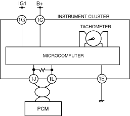
System Wiring Diagram
Operation
• The engine speed signal sent from the PCM via the CAN system is input to the microcomputer in the instrument cluster. The microcomputer calculates the current engine speed based on the engine speed signal, and sends an output signal to the tachometer.
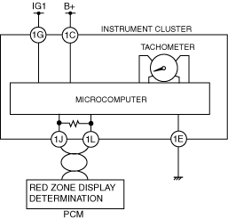
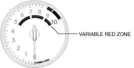
Variable Red Zone Control
• The PCM determines the red zone of the engine speed based on the engine coolant temperature signal from the ECT sensor, and outputs a variable red zone display request signal to the instrument cluster via CAN system.
• The instrument cluster switches the variable red zone display in the tachometer based on the red zone display request signal input from the PCM.
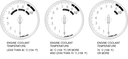
• Variable red zone has three display patterns that are switched according to the engine coolant temperature.
|
Engine coolant temperature
|
Range of variable red zone
|
|
5MT, 6AT
|
6MT
|
|
Less than 40 °C {104 °F}
|
5,000 rpm
|
5,000 rpm
|
|
40 °C {104 °F} or more and less than 70°C {158 °F}
|
6,500 rpm
|
7,000 rpm
|
|
70 °C {158 °F} or more
|
7,500 rpm
|
9,000 rpm
|