 |
ar8wzn00000205
ON-BOARD DIAGNOSTIC FUNCTION [CAN (CONTROLLER AREA NETWORK)]
id094000104100
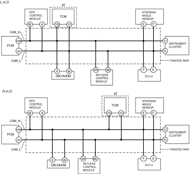
Block Diagram
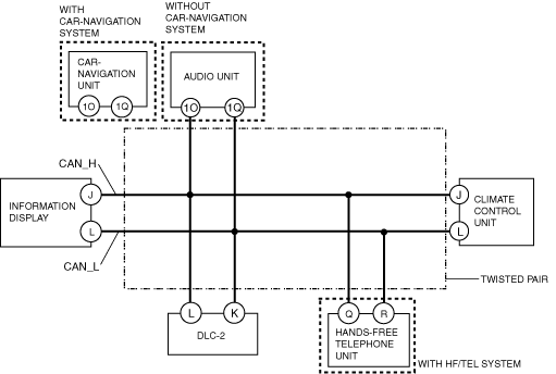
HS-CAN
ar8wzn00000205
|
MS-CAN
ar8wzn00000206
|
On-Board Diagnostic Function
Malfunction detection function
Fail-safe function
Memory function
Self-malfunction diagnostic function
HS-CAN
|
DTC Output Unit |
DTC |
Malfunction location |
|---|---|---|
|
Instrument cluster
|
U1900
|
CAN system communication error
|
|
U2023
|
Abnormal message from PCM
|
|
|
U2064
|
Warning light illumination request signal from other modules
|
|
|
U2516
|
CAN system wiring harness open or short circuit
|
|
|
PCM
|
U0073
|
Module communication error (CAN bus)
|
|
U0101
|
Communication error to TCM
|
|
|
U0121
|
DSC HU/CM communication error
|
|
|
U0155
|
Communication error to instrument cluster
|
|
|
U0167
|
Communication error to keyless control module
|
|
|
DSC HU/CM
|
U0073
|
Module communication error (CAN bus)
|
|
U0100
|
PCM communication error
|
|
|
U0101
|
Communication error to TCM
|
|
|
U0155
|
Communication error to instrument cluster
|
|
|
U1900
|
CAN system communication error
|
|
|
U2023
|
Abnormal message from PCM
|
|
|
EPS control module
|
U0073
|
Module communication error (CAN bus)
|
|
U1900
|
CAN system communication error
|
|
|
U2023
|
Abnormal message from PCM
|
|
|
TCM
|
U0073
|
CAN system communication error
|
|
U0100
|
PCM communication error
|
|
|
U0121
|
DSC HU/CM communication error
|
|
|
Keyless control module
|
U0073
|
Module communication error (CAN bus)
|
|
U0100
|
PCM communication error
|
|
|
U1147
|
Communication error to PCM
|
|
|
U2023
|
Abnormal message from PCM
|
|
|
U2510
|
Communication error to PCM
|
|
|
Steering angle sensor
|
U1900
|
CAN system communication error
|
|
U2516
|
CAN system wiring harness open or short circuit
|
MS-CAN
|
DTC Output Unit |
DTC |
Malfunction location |
|---|---|---|
|
Information display
|
U0164
|
Communication error to climate control unit
|
|
U0184
|
Communication error to audio unit
|
|
|
U2516
|
CAN system communication error
|
|
|
Audio unit
|
16:Er12
|
CAN system communication error
|
|
Car-navigation unit
|
Device code 16/error code 12
|
CAN system communication error
|
|
Device code 17/error code 11
|
Communication error to instrument cluster
|
|
|
Hands-free telephone unit (with audio unit)
|
26:Er81
|
CAN system communication error
|
|
Hands-free telephone unit (with car-navigation unit)
|
Device code 26/error code 81
|
CAN system communication error
|
PID/data monitoring function
PID/data monitor table
|
PID name (definition) |
Condition |
Specification |
PID monitor module |
Terminal |
|---|---|---|---|---|
|
ABS_MSG
(Missing message from the DSC HU/CM)
|
Present
|
Circuit in the DSC HU/CM is normal.
|
Instrument cluster
|
• DSC HU/CM: X, W
• Instrument cluster: 1J, 1L
|
|
Not Present
|
Circuit in the DSC HU/CM is disable.
|
|||
|
EPS_MSG
(Missing message from the EPS control module)
|
Present
|
Circuit in the EPS control module is normal
|
• EPS control module: M, K
• Instrument cluster: 1J, 1L
|
|
|
Not Present
|
Circuit in the EPS control module is disable
|
|||
|
PCM_MSG
(Missing message from the PCM)
|
Present
|
Circuit in the PCM is normal.
|
• PCM: 1AM, 1AI
• Instrument cluster: 1J, 1L
|
|
|
Not Present
|
Circuit in the PCM is disable.
|
|||
|
TCM_MSG
(Missing message from the TCM)
|
Present
|
Circuit in the TCM is normal.
|
• TCM: 1G, 1C
• Instrument cluster: 1J, 1L
|
|
|
Not Present
|
Circuit in the TCM is disable.
|
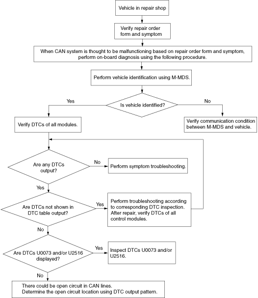
Narrowing down malfunction locations
Troubleshooting procedure
ar8wzn00000544
|
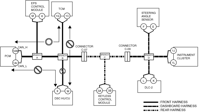
Example (L.H.D.): DSC HU/CM-related wiring harness open circuit (if DTC is output)
1. Verify the CAN system-related module DTCs and the failed module using the Mazda Modular Diagnostic System (M-MDS).
|
Module |
Displayed DTC |
Probable malfunction location |
|---|---|---|
|
PCM
|
U0121
|
DSC HU/CM communication error
|
|
TCM
|
U0121
|
DSC HU/CM communication error
|
|
Module |
Fail |
|---|---|
|
DSC HU/CM
|
×
|
ar8wzn00000207
|
2. The wiring harness between the DSC HU/CM and branch B, or the DSC HU/CM itself could have a malfunction because the DTCs indicating a communication error between the DSC HU/CM and PCM/TCM, in addition to "Fail" on the DSC HU/CM, are displayed even though communication between the PCM and TCM is normal.
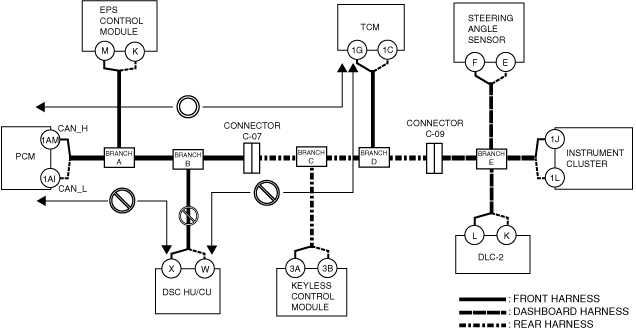
Example (R.H.D.): DSC HU/CM-related wiring harness open circuit (if DTC is output)
1. Verify the CAN system-related module DTCs and the failed module using the Mazda Modular Diagnostic System (M-MDS).
|
Module |
Displayed DTC |
Probable malfunction location |
|---|---|---|
|
PCM
|
U0121
|
DSC HU/CM communication error
|
|
TCM
|
U0121
|
DSC HU/CM communication error
|
|
Module |
Fail |
|---|---|
|
DSC HU/CM
|
×
|
ar8wzn00000208
|
2. The wiring harness between the DSC HU/CM and branch B, or the DSC HU/CM itself could have a malfunction because the DTCs indicating a communication error between the DSC HU/CM and PCM/TCM, in addition to "Fail" on the DSC HU/CM, are displayed even though communication between the PCM and TCM is normal.