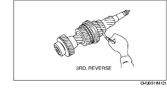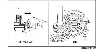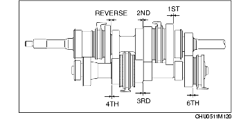
1. Measure the thrust clearance of each gear using a feeler gauge and a dial gauge as shown in the figure.
Thrust clearance
mm {in}|
Gear
|
Thrust clearance
|
|---|---|
|
1st
|
0.15-0.40 {0.006-0.015}
|
|
2nd
|
0.10-0.45 {0.004-0.017}
|
|
3rd
|
0.10-0.35 {0.004-0.013}
|
|
4th
|
0.10-0.35 {0.004-0.013}
|
|
6th
|
0.10-0.40 {0.004-0.015}
|
|
Reverse
|
0.10-0.45 {0.004-0.017}
|
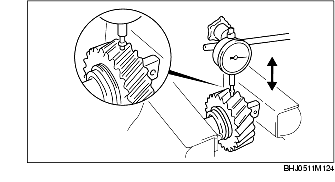
1. Measure the radial clearance of each gear using a dial gauge.
Radial clearance
mm {in}1. Secure the reverse idler gear and reverse idler shaft in a vise, and measure the radial clearance using a dial gauge.
• If not within the specification, replace the reverse idler gear and the reverse idler shaft.
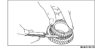
1. Set the synchronizer ring evenly in the gear, and measure the clearance between the synchronizer ring and flank surface of the gear all around the circumference using a feeler gauge.
Clearance
mm {in}• If not within the specification, replace the synchronizer ring.
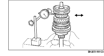
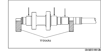
1. Hold the mainshaft with the V-blocks and measure the runout using a dial gauge as shown in the figure.
• If it exceeds the maximum specification, replace the mainshaft.
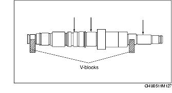
1. Hold the countershaft with the V-blocks and measure the runout using a dial gauge as shown in the figure.
• If it exceeds the maximum specification, replace the countershaft.
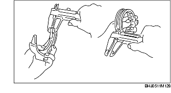
1. Measure the shift fork thickness and the groove width of the clutch hub sleeve with a vernier caliper, and calculate the clearance.
• If not within the specification, replace the clutch hub sleeve and shift fork.