CONTROL VALVE BODY ASSEMBLY
BHE051321100A04
-
Caution
-
• Denting or scratching the control valve body components will reduce the performance of the transmission to shift properly. When handling these components or the valve body that contains them, be careful not to drop or hit them.
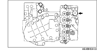
1. Apply ATF to new O-rings, and install them to the solenoids.
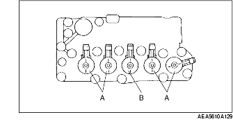
2. Install the solenoid as shown in the figure.
|
Solenoid
|
Color of connector
|
|
A
|
Brown
|
|
B
|
Gray
|
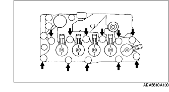
3. Install the harness bracket and the fix plate.
-
Tightening torque
-
6.9-8.8 N·m {71-89 kgf·cm, 62-77 in·lbf}
4. Install the oil strainer.
-
Tightening torque
-
6.9-8.8 N·m {71-89 kgf·cm, 62-77 in·lbf}
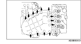
5. Install the oil pressure switch.
-
Tightening torque
-
4.0-4.9 N·m {40-50 kgf·cm, 35-43 in·lbf}
6. Install the pressure control solenoid.
-
Tightening torque
-
6.9-8.8 N·m {71-89 kgf·cm, 62-77 in·lbf}
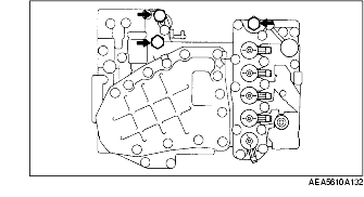
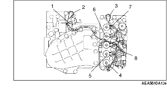
7. Install the harness component as shown in the figure.
|
No.
|
Name
|
Color of harness
|
|
1
|
Oil pressure switch B
|
Brown
|
|
2
|
Oil pressure switch C
|
Gray
|
|
3
|
Oil pressure switch F
|
Pink
|
|
4
|
Shift solenoid A
|
Orange
|
|
5
|
Shift solenoid B
|
Blue
|
|
6
|
Shift solenoid C
|
Green
|
|
7
|
Shift solenoid F
|
Red
|
|
8
|
TCC solenoid
|
Yellow
|