 |
ar8wzw00001480
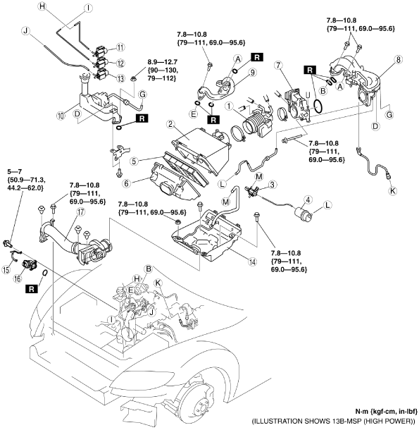
INTAKE-AIR SYSTEM REMOVAL/INSTALLATION
id011300801900
1. Remove in the order indicated in the table.
2. Install in the reverse order of removal.
3. Add the engine coolant to the cooling system filler neck and the coolant reserve tank to replace that during servicing.
4. Inspect the engine coolant level. (See ENGINE COOLANT LEVEL INSPECTION.)
5. Inspect for engine coolant leakage. (See ENGINE COOLANT LEAKAGE INSPECTION.)
ar8wzw00001480
|
|
1
|
Air hose
(See Air Hose Installation Note.)
|
|
2
|
Air cleaner cover
|
|
3
|
VFAD solenoid valve (13B-MSP (High power))
|
|
4
|
Vacuum chamber (13B-MSP (High power))
|
|
5
|
Air cleaner element
|
|
6
|
Air cleaner case
|
|
7
|
Throttle body
(See Throttle Body Removal Note.)
|
|
8
|
Extension manifold (upper)
|
|
9
|
Extension manifold (lower) (13B-MSP (High power))
|
|
10
|
Oil filler pipe
|
|
11
|
AIR solenoid valve
|
|
12
|
SSV solenoid valve
|
|
13
|
VDI solenoid valve
|
|
14
|
Air cleaner insulator
|
|
15
|
Bracket (13B-MSP (High power))
|
|
16
|
APV motor (13B-MSP (High power))
|
|
17
|
Fresh-air duct
(See Fresh-air Duct Removal Note.)
|
Throttle Body Removal Note
1. Wrap a clean cloth around the cooling system cap and release the pressure by loosening the cap slowly.
2. Remove the water hose from the throttle body and plug the water hose quickly.
3. Remove the throttle body.
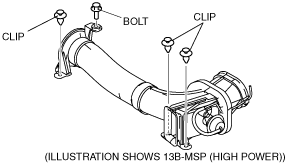
Fresh-air Duct Removal Note
1. Remove the front bumper. (See FRONT BUMPER REMOVAL/INSTALLATION.)
Fresh-air Duct Installation Note
1. Install the clips.
2. Tighten the bolt to the specified torque.
ar8wzw00001481
|
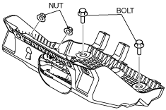
Air Cleaner Insulator Installation Note
1. Temporarily tighten nuts.
2. Temporarily tighten bolts.
3. Tighten the nuts to the specified torque.
4. Tighten the bolts to the specified torque.
ar8wzw00001482
|
Throttle Body Installation Note
1. Install the throttle body.
2. Remove the plug from the water hose and install the water hose to the throttle body quickly.
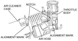
Air Hose Installation Note
1. Align the alignment marks with the air hose notches.
ar8wzw00001483
|