 |
ghe140zt005
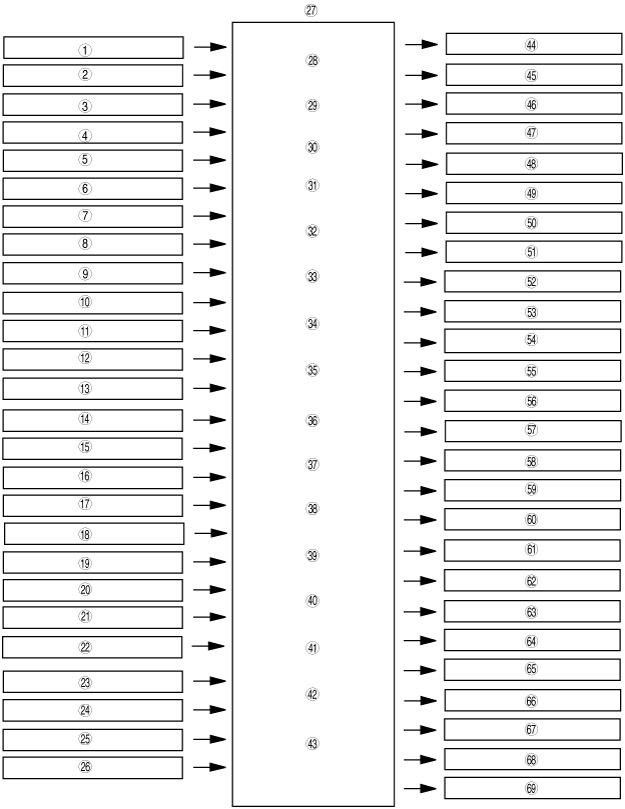
ENGINE CONTROL SYSTEM BLOCK DIAGRAM
id014000100500
ghe140zt005
|
|
1
|
Neutral switch (MT)
|
|
2
|
CPP switch (MT)
|
|
3
|
SSV switch
|
|
4
|
APV position sensor (13B-MSP (High power))
|
|
5
|
ECT sensor
|
|
6
|
IAT sensor
|
|
7
|
TP sensor
|
|
8
|
APP sensor
|
|
9
|
MAF sensor
|
|
10
|
A/F sensor
|
|
11
|
HO2S
|
|
12
|
BARO sensor
|
|
13
|
KS
|
|
14
|
Eccentric shaft position sensor
|
|
15
|
Metering oil pump switch
|
|
16
|
Ignition switch
|
|
17
|
P/S signal (CAN signal)
|
|
18
|
Vehicle speed signal (CAN signal)
|
|
19
|
Cruise control switch
|
|
20
|
TR switch signal (AT vehicles) (CAN signal)
|
|
21
|
Brake switch No.1 (CAN signal)
|
|
22
|
Brake switch No.2 (Analog signal)
|
|
23
|
TCM (AT) (CAN SIGNAL)
|
|
24
|
DSC HU/CM (With DSC) (CAN signal)
|
|
25
|
A/C AMPLIFIER (A/C switch signal)
|
|
26
|
Refrigerant pressure switch (Medium pressure switch)
|
|
27
|
PCM
|
|
28
|
Main relay control
|
|
29
|
Drive-by-wire control
|
|
30
|
Drive-by-wire relay control
|
|
31
|
S-DAIS control
|
|
32
|
Fuel injection control
|
|
33
|
Fuel pump control
|
|
34
|
Fuel pump speed control
|
|
35
|
Ignition timing control
|
|
36
|
AIR control
|
|
37
|
Evaporative purge control
|
|
38
|
Metering oil pump control
|
|
39
|
A/F sensor heater control
|
|
40
|
HO2S heater control
|
|
41
|
A/C cut-off control
|
|
42
|
Electrical fan control
|
|
43
|
Generator control
|
|
44
|
Main relay
|
|
45
|
Drive-by-wire relay
|
|
46
|
Throttle valve actuator
|
|
47
|
SSV solenoid valve
|
|
48
|
APV motor (13B-MSP (High power))
|
|
49
|
VDI solenoid valve
|
|
50
|
VFAD solenoid valve (13B-MSP (High power))
|
|
51
|
Fuel injector (Primary 1)
|
|
52
|
Fuel injector (Primary 2) (13B-MSP (High power))
|
|
53
|
Fuel injector (Secondary)
|
|
54
|
Fuel pump relay
|
|
55
|
Fuel pump speed control relay
|
|
56
|
Ignition coil (L/F)
|
|
57
|
Ignition coil (T/F)
|
|
58
|
Ignition coil (L/R)
|
|
59
|
Ignition coil (T/R)
|
|
60
|
AIR pump relay
|
|
61
|
AIR solenoid valve
|
|
62
|
Stepping motor (In metering oil pump)
|
|
63
|
A/F sensor heater
|
|
64
|
HO2S heater
|
|
65
|
Purge solenoid valve
|
|
66
|
A/C relay
|
|
67
|
Cooling fan relay No.1
|
|
68
|
Cooling fan relay No.2
|
|
69
|
Cooling fan relay No.3
|