 |
ar8wzw00001392
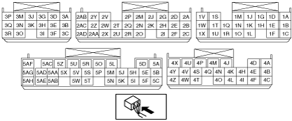
PCM INSPECTION
id014000802500
Not Using the WDS or Equivalent
PCM terminal voltage table (Reference)
ar8wzw00001392
|
|
Terminal |
Signal name |
Connected to |
Measurement condition |
Voltage (V) |
Inspection item(s) |
|
|---|---|---|---|---|---|---|
|
1A
|
—
|
—
|
—
|
—
|
—
|
|
|
1B
|
Throttle control (+)
|
Throttle body (Throttle valve actuator)
|
• Throttle valve actuator
• Related wiring harnesses
|
|||
|
1C
|
Throttle control (–)
|
Throttle body (Throttle valve actuator)
|
• Throttle valve actuator
• Related wiring harnesses
|
|||
|
1D
|
SSV switch
|
SSV switch
|
Idling after warm-up
|
The SSV actuator rod is completely pulled out.
|
1.0 or less
|
• SSV switch
• Related wiring harnesses
|
|
The SSV actuator rod is pulled in.
|
B+
|
|||||
|
1E
|
—
|
—
|
—
|
—
|
—
|
|
|
1F
|
Knock sensor (–)
|
Knock sensor
|
Under any condition
|
1.0 or less
|
• Knock sensor
• Related wiring harnesses
|
|
|
1G
|
Shield
|
—
|
—
|
—
|
—
|
|
|
1H
|
—
|
—
|
—
|
—
|
—
|
|
|
1I
|
—
|
—
|
—
|
—
|
—
|
|
|
1J
|
Throttle valve opening angle No. 1
|
Throttle body (TP sensor)
|
Ignition switch at ON
|
When the accelerator pedal is depressed.
|
3.825—4.095
|
• TP sensor
• Related wiring harnesses
|
|
When the accelerator pedal is released.
|
0.4—0.8
|
|||||
|
1K
|
—
|
—
|
—
|
—
|
—
|
|
|
1L
|
SSV control
|
SSV solenoid valve
|
High engine speed and high load after warm-up
|
1.0 or less
|
• SSV solenoid valve
• Related wiring harnesses
|
|
|
Idling
|
B+
|
|||||
|
1M
|
Throttle valve opening angle No. 2
|
Throttle body (TP sensor)
|
Ignition switch at ON
|
When the accelerator pedal is depressed.
|
4.033—4.303
|
• TP sensor
• Related wiring harnesses
|
|
When the accelerator pedal is released.
|
1.18—1.78
|
|||||
|
1N
|
—
|
—
|
—
|
—
|
—
|
|
|
1O
|
AIR control
|
AIR solenoid valve
|
During the specified period after cold start
|
1.0 or less
|
• AIR solenoid valve
• Related wiring harnesses
|
|
|
Idling after warm-up
|
B+
|
|||||
|
1P
|
—
|
—
|
—
|
—
|
—
|
|
|
1Q
|
TP sensor power supply
|
Throttle body (TP sensor)
|
Under any condition
|
Approx. 5.0
|
• TP sensor
• Related wiring harnesses
|
|
|
1R
|
—
|
—
|
—
|
—
|
—
|
|
|
1S
|
APV position sensor power supply *3
|
APV motor (APV position sensor)
|
Under any condition
|
Approx. 5.0
|
• APV position sensor
• Related wiring harnesses
|
|
|
—*4
|
—
|
—
|
—
|
—
|
||
|
1T
|
Knock sensor (+)
|
Knock sensor
|
Idling after warm-up
|
Approx. 2.45
|
• Knock sensor
• Related wiring harnesses
|
|
|
1U
|
Sensor GND
|
ECT sensor, HO2S, metering oil pump switch, APV position sensor
|
Under any condition
|
1.0 or less
|
• Related wiring harnesses
|
|
|
1V
|
A/F sensor heater control
|
A/F sensor heater
|
• A/F sensor
• Related wiring harnesses
|
|||
|
1W
|
VDI control
|
VDI solenoid valve
|
High engine speed after warm-up
|
1.0 or less
|
• VDI solenoid valve
• Related wiring harnesses
|
|
|
Idling
|
B+
|
|||||
|
1X
|
—
|
—
|
—
|
—
|
—
|
|
|
1Y
|
—
|
—
|
—
|
—
|
—
|
|
|
1Z
|
—
|
—
|
—
|
—
|
—
|
|
|
2A
|
HO2S heater control
|
HO2S heater
|
Idling after warm-up
|
1.0 or less
|
• HO2S
• Related wiring harnesses
|
|
|
High load
|
B+
|
|||||
|
2B
|
A/F sensor
|
A/F sensor
|
Idling after warm-up
|
Approx. 2.8
|
• A/F sensor
• Related wiring harnesses
|
|
|
2C
|
A/F sensor
|
A/F sensor
|
Idling after warm-up
|
Approx. 2.4
|
• A/F sensor
• Related wiring harnesses
|
|
|
2D
|
Fuel injector (RS) control
|
Fuel injector (RS)
|
• Fuel injector
• Related wiring harnesses
|
|||
|
2E
|
Oil pressure switch
|
Oil pressure switch
|
Idling
|
The engine oil pressure is at the specified or more.
|
B+
|
• Oil pressure switch
• Related wiring harnesses
|
|
The engine oil pressure is less than the specified.
|
1.0 or less
|
|||||
|
2F
|
TP sensor GND
|
Throttle body (TP sensor)
|
Under any condition
|
1.0 or less
|
• TP sensor
• Related wiring harnesses
|
|
|
2G
|
Fuel injector (FS) control
|
Fuel injector (FS)
|
• Fuel injector
• Related wiring harnesses
|
|||
|
2H
|
Shield
|
—
|
—
|
—
|
—
|
|
|
2I
|
Field coil control
|
Generator (D terminal)
|
• Generator
• Related wiring harnesses
|
|||
|
2J
|
Fuel injector (RP1) control
|
Fuel injector (RP1)
|
• Fuel injector
• Related wiring harnesses
|
|||
|
2K
|
ECT sensor
|
ECT sensor
|
Ignition switch at ON
|
ECT 0 °C {32 °F}
|
Approx. 4.0
|
• ECT sensor
• Related wiring harnesses
|
|
ECT 20 °C {68 °F}
|
Approx. 3.1
|
|||||
|
ECT 40 °C {104 °F}
|
Approx. 2.1
|
|||||
|
ECT 60 °C {140 °F}
|
Approx. 1.4
|
|||||
|
ECT 80 °C {176 °F}
|
Approx. 0.9
|
|||||
|
ECT 100 °C {212 °F}
|
Approx. 0.5
|
|||||
|
2L
|
—
|
—
|
—
|
—
|
—
|
|
|
2M
|
Fuel injector (FP1) control
|
Fuel injector (FP1)
|
• Fuel injector
• Related wiring harnesses
|
|||
|
2N
|
Metering oil pump switch
|
Metering oil pump (Metering oil pump switch)
|
Idling
|
Only when the metering oil pump is commanded to maximum position
|
B+
|
• Metering oil pump switch
• Related wiring harnesses
|
|
Except above
|
1.0 or less
|
|||||
|
2O
|
Neutral switch*1
|
Neutral switch
|
Idling
|
Neutral
|
1.0 or less
|
• Neutral switch
• Related wiring harnesses
|
|
Except above
|
B+
|
|||||
|
—*2
|
—
|
—
|
—
|
—
|
||
|
2P
|
Purge solenoid valve control
|
Purge solenoid valve
|
• Purge solenoid valve
• Related wiring harnesses
|
|||
|
2Q
|
HO2S
|
HO2S
|
Idling after warm-up
|
0.5—1.0
|
• HO2S
• Related wiring harnesses
|
|
|
2R
|
Oil-level switch
|
Oil-level switch
|
Ignition switch at ON
|
The engine oil amount is more than the L mark on the dipstick.
|
1.0 or less
|
• Oil-level switch
• Related wiring harnesses
|
|
The engine oil amount is low.
|
B+
|
|||||
|
2S
|
—
|
—
|
—
|
—
|
—
|
|
|
2T
|
Generator output voltage
|
Generator (Terminal P)
|
• Generator
• Related wiring harnesses
|
|||
|
2U
|
Eccentric shaft position sensor (+)
|
Eccentric shaft position sensor
|
• Eccentric shaft position sensor
• Related wiring harnesses
|
|||
|
2V
|
Metering oil pump control 3
|
Metering oil pump
|
• Metering oil pump
• Related wiring harnesses
|
|||
|
2W
|
Metering oil pump control 1
|
Metering oil pump
|
• Metering oil pump
• Related wiring harnesses
|
|||
|
2X
|
Eccentric shaft position sensor (–)
|
Eccentric shaft position sensor
|
Under any condition
|
1.0 or less
|
• Eccentric shaft position sensor
• Related wiring harnesses
|
|
|
2Y
|
Metering oil pump control 4
|
Metering oil pump
|
• Metering oil pump
• Related wiring harnesses
|
|||
|
2Z
|
Ignition coil (L/R) control
|
Ignition coil
|
• Ignition coil
• Related wiring harnesses
|
|||
|
2AA
|
Ignition coil (L/F) control
|
Ignition coil
|
• Ignition coil
• Related wiring harnesses
|
|||
|
2AB
|
Metering oil pump control 2
|
Metering oil pump
|
• Metering oil pump
• Related wiring harnesses
|
|||
|
2AC
|
Ignition coil (T/R) control
|
Ignition coil
|
• Ignition coil
• Related wiring harnesses
|
|||
|
2AD
|
Ignition coil (T/F) control
|
Ignition coil
|
• Ignition coil
• Related wiring harnesses
|
|||
|
3A
|
Fuel injector (FP2) control*3
|
Fuel injector (FP2)
|
• Fuel injector
• Related wiring harnesses
|
|||
|
—*4
|
—
|
—
|
—
|
—
|
||
|
3B
|
APV opening angle*3
|
APV motor (APV position sensor)
|
High engine speed
|
1.5 or less
|
• APV position sensor
• Related wiring harnesses
|
|
|
Idling
|
1.5 or more
|
|||||
|
—*4
|
—
|
—
|
—
|
—
|
||
|
3C
|
—
|
—
|
—
|
—
|
—
|
|
|
3D
|
Fuel injector (RP2) control *3
|
Fuel injector (RP2)
|
• Fuel injector
• Related wiring harnesses
|
|||
|
—*4
|
—
|
—
|
—
|
—
|
||
|
3E
|
—
|
—
|
—
|
—
|
—
|
|
|
3F
|
—
|
—
|
—
|
—
|
—
|
|
|
3G
|
APV motor control (+)*3
|
APV motor
|
• APV motor
• Related wiring harnesses
|
|||
|
—*4
|
—
|
—
|
—
|
—
|
||
|
3H
|
—
|
—
|
—
|
—
|
—
|
|
|
3I
|
—
|
—
|
—
|
—
|
—
|
|
|
3J
|
APV motor control (–)*3
|
APV motor
|
• APV motor
• Related wiring harnesses
|
|||
|
—*4
|
—
|
—
|
—
|
—
|
||
|
3K
|
—
|
—
|
—
|
—
|
—
|
|
|
3L
|
—
|
—
|
—
|
—
|
—
|
|
|
3M
|
—
|
—
|
—
|
—
|
—
|
|
|
3N
|
—
|
—
|
—
|
—
|
—
|
|
|
3O
|
—
|
—
|
—
|
—
|
—
|
|
|
3P
|
—
|
—
|
—
|
—
|
—
|
|
|
3Q
|
—
|
—
|
—
|
—
|
—
|
|
|
3R
|
—
|
—
|
—
|
—
|
—
|
|
|
3S
|
—
|
—
|
—
|
—
|
—
|
|
|
3T
|
—
|
—
|
—
|
—
|
—
|
|
|
3U
|
—
|
—
|
—
|
—
|
—
|
|
|
3 V
|
—
|
—
|
—
|
—
|
—
|
|
|
3W
|
—
|
—
|
—
|
—
|
—
|
|
|
3X
|
—
|
—
|
—
|
—
|
—
|
|
|
3Y
|
—
|
—
|
—
|
—
|
—
|
|
|
3Z
|
—
|
—
|
—
|
—
|
—
|
|
|
4A
|
GND
|
GND
|
Under any condition
|
1.0 or less
|
• Related wiring harnesses
|
|
|
4B
|
—
|
—
|
—
|
—
|
—
|
|
|
4C
|
Drive-by-wire relay control
|
Drive-by-wire relay
|
Ignition switch at ON
|
When the drive-by-wire system has a malfunction.
|
1.0 or less
|
• Drive-by-wire relay
• Related wiring harnesses
|
|
Except above
|
B+
|
|||||
|
4D
|
—
|
—
|
—
|
—
|
—
|
|
|
4E
|
Main relay control
|
Main relay
|
Ignition switch at ON
|
No malfunction
|
1.0 or less
|
• Main relay
• Related wiring harnesses
|
|
Malfunctioning
|
B+
|
|||||
|
4F
|
Clutch switch*1
|
Clutch switch
|
Ignition switch at ON
|
The clutch pedal is depressed.
|
1.0 or less
|
• Clutch switch
• Related wiring harnesses
|
|
Except above
|
B+
|
|||||
|
—*2
|
—
|
—
|
—
|
—
|
||
|
4G
|
—
|
—
|
—
|
—
|
—
|
|
|
4H
|
—
|
—
|
—
|
—
|
—
|
|
|
4I
|
—
|
—
|
—
|
—
|
—
|
|
|
4J
|
GND
|
GND
|
Under any condition
|
1.0 or less
|
• Related wiring harnesses
|
|
|
4K
|
BARO sensor power supply
|
BARO sensor
|
Under any condition
|
Approx. 5.0
|
• BARO sensor
• Related wiring harnesses
|
|
|
4L
|
—
|
—
|
—
|
—
|
—
|
|
|
4M
|
Fuel pump speed control
|
Fuel pump speed control relay
|
High engine speed and high load
|
1.0 or less
|
• Fuel pump speed control relay
• Related wiring harnesses
|
|
|
Idling
|
B+
|
|||||
|
4N
|
—
|
—
|
—
|
—
|
—
|
|
|
4O
|
AIR pump control
|
AIR pump relay
|
During the specified period after sold start
|
1.0 or less
|
• AIR pump relay
• Related wiring harnesses
|
|
|
Idling after warm-up
|
B+
|
|||||
|
4P
|
Brake switch*7
|
Brake switch
|
When the brake pedal is depressed.
|
B+
|
• Brake switch
• Related wiring harnesses
|
|
|
Except above
|
1.0 or less
|
|||||
|
—*8
|
—
|
—
|
—
|
—
|
||
|
4Q
|
IG1
|
Ignition relay
|
Ignition switch at ON
|
B+
|
• Ignition relay
• Related wiring harnesses
|
|
|
Except above
|
1.0 or less
|
|||||
|
4R
|
—
|
—
|
—
|
—
|
—
|
|
|
4S
|
CAN_L
|
—
|
Because this terminal is for communication, good/no good judgment by terminal voltage is not possible.
|
—
|
• Related wiring harnesses
|
|
|
4T
|
Coolant level switch
|
Coolant level switch
|
Ignition switch at ON
|
Engine coolant level in the coolant reserve tank is more than the L mark.
|
B+
|
• Coolant level switch
• Related wiring harnesses
|
|
Engine coolant level in the coolant reserve tank is at the L mark or less.
|
1.0 or less
|
|||||
|
4U
|
Sensor GND
|
MAF sensor, BARO sensor, IAT sensor
|
Under any condition
|
1.0 or less
|
• Related wiring harnesses
|
|
|
4V
|
CAN_H
|
—
|
Because this terminal is for communication, good/no good judgment by terminal voltage is not possible.
|
—
|
• Related wiring harnesses
|
|
|
4W
|
A/C control
|
Refrigerant pressure switch (high pressure and low pressure)
|
Idling
|
A/C switch off
|
B+
|
• Refrigerant pressure switch
• Related wiring harnesses
|
|
A/C switch and fan switch on
|
1.0 or less
|
|||||
|
4X
|
APP sensor 2 power supply
|
APP sensor
|
Under any condition
|
Approx. 5.0
|
• APP sensor
• Related wiring harnesses
|
|
|
4Y
|
APP sensor 1 power supply
|
APP sensor
|
Under any condition
|
Approx. 5.0
|
• APP sensor
• Related wiring harnesses
|
|
|
4Z
|
A/C load
|
Refrigerant pressure switch (medium pressure)
|
Idling
|
Refrigerant pressure is 1.11 MPa {11.3 kgf/cm2, 161 psi} or less.
|
B+
|
• Refrigerant pressure switch
• Related wiring harnesses
|
|
Refrigerant pressure is 1.60 MPa {16.3 kgf/cm2, 232 psi} or more.
|
1.0 or less
|
|||||
|
5A
|
Starter relay*10
|
Starter relay
|
Ignition switch is turned to START using key registered in immobilizer system
|
1.0 or less
|
• Starter relay
• Related wiring harnesses
|
|
|
Ignition switch is turned to START using key not registered in immobilizer system
|
B+
|
|||||
|
—*11
|
—
|
—
|
—
|
—
|
||
|
5B
|
—
|
—
|
—
|
—
|
—
|
|
|
5C
|
APP sensor 2
|
APP sensor
|
Ignition switch at ON
|
When the accelerator pedal is depressed.
|
3.23—3.38
|
• APP sensor
• Related wiring harnesses
|
|
When the accelerator pedal is released.
|
1.005—1.105
|
|||||
|
5D
|
GND
|
GND
|
Under any condition
|
1.0 or less
|
• Related wiring harnesses
|
|
|
5E
|
—
|
—
|
—
|
—
|
—
|
|
|
5F
|
APP sensor 1
|
APP sensor
|
Ignition switch at ON
|
When the accelerator pedal is depressed.
|
3.78—3.93
|
• APP sensor
• Related wiring harnesses
|
|
When the accelerator pedal is released.
|
1.555—1.655
|
|||||
|
5G
|
—
|
—
|
—
|
—
|
—
|
|
|
5H
|
Drive-by-wire relay control
|
Drive-by-wire relay
|
Ignition switch at ON
|
There is a malfunction in the drive-by-wire system.
|
1.0 or less
|
• Drive-by-wire relay
• Related wiring harnesses
|
|
Except above
|
B+
|
|||||
|
5I
|
—
|
—
|
—
|
—
|
—
|
|
|
5J
|
Backup power supply (KAM)
|
Battery
|
Under any condition
|
B+
|
• Battery
• Related wiring harnesses
|
|
|
5K
|
IAT sensor
|
MAF/IAT sensor
|
Ignition switch at ON
|
IAT 0 °C {32 °F}
|
Approx. 3.4
|
• IAT sensor
• Related wiring harnesses
|
|
IAT 20 °C {68 °F}
|
Approx. 2.4
|
|||||
|
IAT 40 °C {104 °F}
|
Approx. 1.5
|
|||||
|
IAT 60 °C {140 °F}
|
Approx. 0.9
|
|||||
|
IAT 80 °C {176 °F}
|
Approx. 0.5
|
|||||
|
IAT 100 °C {212 °F}
|
Approx. 0.3
|
|||||
|
5L
|
Fuel pump relay control*11
|
Fuel pump relay
|
Engine runs.
|
1.0 or less
|
• Fuel pump relay
• Related wiring harnesses
|
|
|
Engine stops.
|
B+
|
|||||
|
—*10
|
—
|
—
|
—
|
—
|
||
|
5M
|
—
|
—
|
—
|
—
|
—
|
|
|
5N
|
MAF sensor
|
MAF sensor
|
MT
|
Idling
|
1.16—1.23
|
• MAF sensor
• Related wiring harnesses
|
|
2,500 rpm
|
1.49—1.64
|
|||||
|
AT
|
Idling
|
1.21—1.29
|
||||
|
2,500 rpm
|
1.54—1.67
|
|||||
|
5O
|
GND
|
GND
|
Under any condition
|
1.0 or less
|
• Related wiring harnesses
|
|
|
5P
|
Fuel pump relay control*10
|
Fuel pump relay
|
Engine runs.
|
1.0 or less
|
• Fuel pump relay
• Related wiring harnesses
|
|
|
Engine stops.
|
B+
|
|||||
|
—*11
|
—
|
—
|
—
|
—
|
||
|
5Q
|
—
|
—
|
—
|
—
|
—
|
|
|
5R
|
GND
|
GND
|
Under any condition
|
1.0 or less
|
• Related wiring harnesses
|
|
|
5S
|
BARO sensor
|
BARO sensor
|
Ignition switch at ON
|
Altitude:0 m {0 ft})
|
3.8—4.2*9
|
• BARO sensor
• Related wiring harnesses
|
|
Altitude:305 m {1,000 ft}
|
3.6—4.0*9
|
|||||
|
Altitude:610 m {2,000 ft}
|
3.5—3.9*9
|
|||||
|
Altitude:914 m {3,000 ft}
|
3.4—3.7*9
|
|||||
|
Altitude:1,219 m {4,000 ft}
|
3.2—3.6*9
|
|||||
|
Altitude:1,524 m {5,000 ft}
|
3.1—3.5*9
|
|||||
|
Altitude:1,829 m {6,000 ft}
|
3.0—3.4*9
|
|||||
|
Altitude:2,134 m {7,000 ft}
|
2.9—3.3*9
|
|||||
|
5T
|
GND
|
GND
|
Under any condition
|
1.0 or less
|
• Related wiring harnesses
|
|
|
5U
|
MAF sensor GND
|
MAF sensor
|
Under any condition
|
1.0 or less
|
• MAF sensor
• Related wiring harnesses
|
|
|
5V
|
Cruise control switch*5
|
Cruise control switch
|
Ignition switch at ON
|
CRUISE MAIN switch pressed in
|
Approx. 0
|
• Cruise control switch
• Related wiring harnesses
|
|
CANCEL switch pressed in
|
0.25—0.26
|
|||||
|
SET/COAST switch pressed in
|
1.16—1.20
|
|||||
|
RES/ACCEL switch pressed in
|
2.47—2.53
|
|||||
|
Except above
|
Approx. 5
|
|||||
|
—*6
|
—
|
—
|
—
|
—
|
||
|
5W
|
ECT (A/C unit)
|
A/C unit
|
Ignition switch at ON
|
ECT 0 °C {32 °F}
|
Approx. 4.0
|
• A/C unit
• Related wiring harnesses
|
|
ECT 20 °C {68 °F}
|
Approx. 3.1
|
|||||
|
ECT 40 °C {104 °F}
|
Approx. 2.1
|
|||||
|
ECT 60 °C {140 °F}
|
Approx. 1.4
|
|||||
|
ECT 80 °C {176 °F}
|
Approx. 0.9
|
|||||
|
ECT 100 °C {212 °F}
|
Approx. 0.5
|
|||||
|
5X
|
Electrical fan control
|
Cooling fan relay
|
The cooling fan is operating.
|
1.0 or less
|
• Cooling fan relay
• Related wiring harnesses
|
|
|
Except above
|
B+
|
|||||
|
5Y
|
—
|
—
|
—
|
—
|
—
|
|
|
5Z
|
VFAD control*3
|
VFAD solenoid valve
|
High engine speed
|
1.0 or less
|
• VFAD solenoid valve
• Related wiring harnesses
|
|
|
Idling
|
B+
|
|||||
|
—*4
|
—
|
—
|
—
|
—
|
||
|
5AA
|
A/C relay
|
A/C relay
|
Ignition switch at ON
|
A/C switch on and fan switch at 1st or higher
|
1.0 or less
|
• A/C relay
• Related wiring harnesses
|
|
Except above
|
B+
|
|||||
|
5AB
|
APP sensor GND 2
|
APP sensor
|
Under any condition
|
1.0 or less
|
• APP sensor
• Related wiring harnesses
|
|
|
5AC
|
Power supply
|
Main relay
|
Under any condition
|
B+
|
• Main relay
• Related wiring harnesses
|
|
|
5AD
|
Electrical fan control
|
Cooling fan relay
|
The cooling fan is operating at high speed.
|
1.0 or less
|
• Cooling fan relay
• Related wiring harnesses
|
|
|
Except above
|
B+
|
|||||
|
5AE
|
APP sensor GND 1
|
APP sensor
|
Under any condition
|
1.0 or less
|
• APP sensor
• Related wiring harnesses
|
|
|
5AF
|
Power supply
|
Main relay
|
Under any condition
|
B+
|
• Main relay
• Related wiring harnesses
|
|
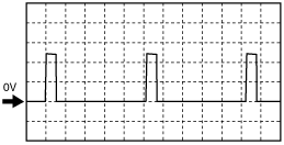
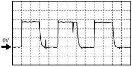
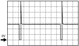
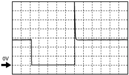
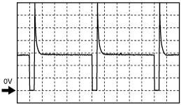
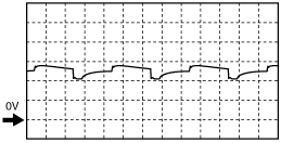
Inspection Using An Oscilloscope (Reference)
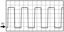
Throttle control (+)
ar8wzw00001393
|
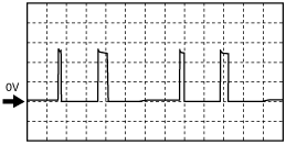
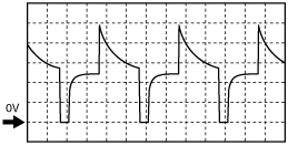
Throttle control (–)
ar8wzw00001394
|
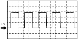
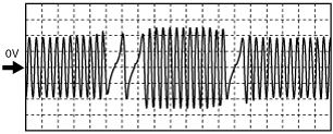
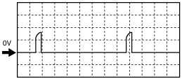
A/F sensor heater control
ar8wzw00001395
|
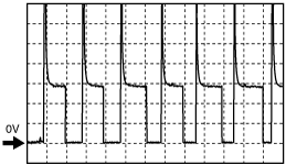
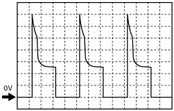
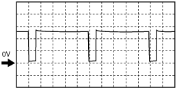
Fuel injector (FS, RS) control
ar8wzw00001396
|
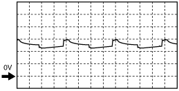
Field coil control (Generator)
ar8wzw00001397
|
Fuel injector (FP1, RP1) control
ar8wzw00001398
|
ar8wzw00001399
|
Purge control
ar8wzw00001400
|
Generator output voltage
ar8wzw00001401
|
Eccentric shaft position sensor
ar8wzw00001402
|
Metering oil pump control 1
ar8wzw00001403
|
Metering oil pump control 2
ar8wzw00001404
|
Metering oil pump control 3
ar8wzw00001405
|
Metering oil pump control 4
ar8wzw00001406
|
Ignition coil (L/F, L/R, T/F, T/R)
ar8wzw00001407
|
Fuel injector (FP2, RF2) control
ar8wzw00001396
|
APV motor control (+)
ar8wzw00001408
|
APV motor control (–)
ar8wzw00001408
|
Using the WDS or Equivalent
1. Connect the WDS or equivalent to the DLC-2.
2. Turn the ignition switch to ON position.
3. Measure the PID value.
PID/DATA monitor table (reference)
|
Monitor item (Definition) |
Unit/Condition |
Condition/Specification (Reference) |
Inspection item(s) |
PCM terminal |
|
|---|---|---|---|---|---|
|
AC_REQ
|
On/Off
|
• Refrigerant pressure is normal pressure. (Refrigerant pressure switch (high, low) is ON.): On
• Except above: Off
|
• Refrigerant pressure switch (high, low)
• A/C amplifier
|
—
|
|
|
ACCS (A/C relay)
|
On/Off
|
• Ignition switch ON: Off
• A/C switch ON and fan switch ON at idling: On
|
• The following PIDs
• A/C relay
|
5AA
|
|
|
AIP RLY (AIR pump relay)
|
On/Off
|
• During the specified period after cold: On
• Idling after warm-up: Off
|
• The following PIDs
• AIR pump relay
|
4O
|
|
|
ALTF (Generator field coil control duty value)
|
%
|
• Ignition switch ON: 0%
• Just after A/C switch ON and fan switch ON at idling: Duty value rises
|
• The following PIDs
|
2I
|
|
|
ALTT V (Generator output voltage)
|
V
|
• Ignition switch ON: 0 V
• Idling: Approx. 14.9 V*1 (E/L not operating)
|
Generator.
|
2T
|
|
|
APP (Accelerator pedal position)
|
%
|
• Accelerator pedal released: 0%
• Accelerator pedal depressed: 100%
|
• The following PIDs
• APP sensor
|
—
|
|
|
APP1 (Accelerator pedal position)
|
%
|
• Accelerator pedal released: 31.1—33.1%
• Accelerator pedal depressed: 75.6—78.6%
|
APP sensor
|
5F
|
|
|
V
|
• Accelerator pedal released: 1.555—1.655 V
• Accelerator pedal depressed: 3.78—3.93 V
|
||||
|
APP2 (Accelerator pedal position)
|
%
|
• Accelerator pedal released: 20.1—22.1%
• Accelerator pedal depressed: 64.6—67.6%
|
APP sensor
|
5C
|
|
|
V
|
• Accelerator pedal released: 1.005—1.105 V
• Accelerator pedal depressed: 3.23—3.38 V
|
||||
|
APV*8
(APV motor)
|
Opening/Closing
|
• High engine speed after warm-up: Opening
• Except above: Closing
|
• The following PIDs
• APV motor
|
3G, 3J
|
|
|
APV_POS*8
(APV position sensor)
|
V
|
• High engine speed after warm-up: 1.5 V or less
• Except above: 1.5 V or more
|
• APV position sensor
|
3B
|
|
|
ARPMDES (Target engine speed)
|
RPM
|
MT
• No load after warm-up: 750—850 rpm
AT
• No load after warm-up: 760—860 rpm
|
• The following PIDs
|
—
|
|
|
B+ (Battery positive voltage)
|
V
|
• Ignition switch ON: B+
|
• Battery
|
5J
|
|
|
BARO (Barometric pressure)
|
kPa, Bar, psi
|
• Ignition switch ON: Indicate the atmospheric pressure
|
• BARO sensor
|
5S
|
|
|
V
|
• Ignition switch ON
|
||||
|
BOO
(Brake switch)
|
On/Off
|
• Brake pedal depressed: On
• Brake pedal released: Off
|
• Brake switch
|
4P
|
|
|
CATT11_DSD
(Estimated catalytic converter temperature)
|
°C
|
°F
|
• Idling after warm-up: Approx. 531 °C {988 °F}
|
• The following PIDs
|
—
|
|
CHRGLP (Generator warning light)
|
On/Off
|
• Ignition switch ON: On
• Idling: Off
|
• Generator warning light
|
—
|
|
|
COLP (Refrigerant pressure switch (middle))
|
On/Off
|
• Refrigerant pressure switch (middle) ON *2 at idling: On
• Refrigerant pressure switch (middle) OFF*3 at idling: Off
|
• Refrigerant pressure switch
|
4Z
|
|
|
CPP*7
(Clutch pedal position)
|
On/Off
|
• Clutch pedal depressed: On
• Clutch pedal released: Off
|
• CPP switch
|
4F
|
|
|
CPP/PNP*7
(Shift lever position)
|
Drive/Neutral
|
• Neutral position: Neutral
• Except above: Drive
|
• Neutral switch
|
2O
|
|
|
DEI (VDI solenoid valve)
|
On/Off
|
• Idling: Off
• High engine speed after warm-up: On
|
• The following PID
• VDI solenoid valve
|
1W
|
|
|
DTCCNT (Number of DTC detected)
|
—
|
—
|
—
|
—
|
|
|
ECT (Engine coolant temperature)
|
°C
|
°F
|
• Ignition switch at ON position: Indicate the ECT
|
• ECT sensor
|
2K
|
|
V
|
• ECT 20 °C {68 °F}: Approx. 3.1 V
• ECT 80 °C {176 °F}: Approx. 0.9 V
|
||||
|
EQ_RAT11
(A/F sensor)
|
—
|
• Idling after worm-up: Approx.1
|
• A/F sensor
|
2B, 2C
|
|
|
ETC_ACT (Electronic throttle control actual)
|
°
|
• CTP: 6.3° or less
• WOT: Approx. 83°
|
• The following PIDs
|
—
|
|
|
ETC_DSD (Electronic throttle control desired)
|
°
|
• CTP: 6.3° or less
• WOT: Approx. 83°
|
• The following PIDs
|
—
|
|
|
%
|
• CTP: 7% or less
• WOT: Approx. 100%
|
||||
|
EVAPCP (Purge solenoid valve duty value)
|
%
|
• Ignition switch ON: 0%
• Increase the engine speed: Duty value rises
|
• The following PIDs
• Purge solenoid valve
|
2P
|
|
|
FAN1
(Cooling fan control)
|
On/Off
|
• The cooling fan is operating: On
• Except above: Off
|
• The following PIDs
• Cooling fan relay No.1
|
5X
|
|
|
FAN2
(Cooling fan control)
|
On/Off
|
• The cooling fan is operating at high speed: On
• Except above: Off
|
• The following PIDs
• Cooling fan relay No.2
|
5AD
|
|
|
FP (Fuel pump relay)
|
On/Off
|
• Ignition switch ON: Off
• Idling: On
• Cranking: On
|
• The following PID
• Fuel pump relay
|
5P*5
5L*6
|
|
|
FPRR (Fuel pump speed control relay)
|
On/Off
|
• Ignition switch ON: Off
• Idling: Off
• Cranking: On
|
• The following PIDs
• Fuel pump speed control relay
|
4M
|
|
|
FUELPW (Fuel injector duration)
|
ms
|
• Cranking (before warm-up [ECT: 20 °C {68 °F}]): Approx. 48 ms
• Cranking after warm-up: Approx. 9.6 ms
• Idling after warm-up: 2.9—3.5 ms
|
• The following PIDs
• Fuel injector
|
2J, 2M
|
|
|
FUELSYS
(Fuel system status)
|
OL/CL/
OL Drive/
OL Fault/
CL Fault
|
• Idling after warm-up: CL
|
• The following PIDs
|
—
|
|
|
GENVDSD
(Generator voltage desired)
|
V
|
• Ignition switch ON: 0 V
• Idling: Approx. 14.9 V*1 (E/L not operating)
|
• The following PIDs
|
—
|
|
|
HTR11
(A/F sensor heater)
|
On/Off
|
• Idling after warm-up: On
|
• The following PIDs
• A/F sensor heater
|
1V
|
|
|
HTR12
(HO2S heater)
|
On/Off
|
• Idling after warm-up: On
|
• The following PIDs
• HO2S heater
|
2A
|
|
|
IAC (Idle air control)
|
%
|
• Ignition switch ON: Approx. 26%
• Idling after warm-up: Approx. 21%
|
• The following PIDs
• Throttle valve actuator
|
1B, 1C
|
|
|
IASV*8
(VFAD solenoid valve)
|
On/Off
|
• High engine speed: On
• Idling: Off
|
• The following PID
• VFAD solenoid valve
|
5Z
|
|
|
IAT
(Intake air temperature)
|
°C
|
°F
|
• Ignition switch at ON position: Indicate the IAT
|
• IAT sensor
|
5K
|
|
V
|
• IAT 20 °C {68 °F}: Approx. 2.4 V
• IAT 40 °C {104 °F}: Approx. 1.5 V
|
||||
|
INGEAR (In gear)
|
On/Off
|
MT
• When the following conditions are satisfied: On
• Except above: Off
AT
• When the following conditions are satisfied: On
• Except above: Off
|
• The following PIDs
|
—
|
|
|
IVS (CTP condition)
|
Idle/
Off Idle
|
• CTP: Idle
• Except above: Off idle
|
• The following PID
|
—
|
|
|
KNOCKR (Knocking retard)
|
°
|
• Ignition switch ON: 0 °
• Idling: 0 °
|
• KS
|
1T
|
|
|
LOAD (Engine load)
|
%
|
MT
• Idling: 18.0—25.0%
• Engine speed 2,500 rpm (no load): 13.5—19.5%
AT
• Idling: 20.0—28.0%
• Engine speed 2,500 rpm (no load): 15.0—21.0%
|
• The following PIDs
|
—
|
|
|
LONGFT1 (long term fuel trim)
|
%
|
• Idling after warm-up: Approx.–12.5—12.5%
|
• The following PIDs
|
—
|
|
|
MAF (Mass airflow)
|
g/s
|
MT
• Idling after warm-up: 3.8—4.7 g/s
• Engine speed 2,500 rpm (no load): 8.7—11.7 g/s
AT
• Idling after warm-up: 4.4—5.3 g/s
• Engine speed 2,500 rpm (no load): 9.5—12.5 g/s
|
• MAF sensor
|
5N
|
|
|
V
|
MT
• Idling after warm-up: 1.16—1.23 V
• Engine speed 2,500 rpm (no load): 1.49—1.64 V
AT
• Idling after warm-up: 1.21—1.29 V
• Engine speed 2,500 rpm (no load): 1.54—1.67 V
|
||||
|
MIL (Malfunction indicator lamp)
|
On/Off
|
• Ignition switch ON: On
• Idling: Off
|
• MIL
|
—
|
|
|
MIL_DIS (Travelled distance since the MIL illuminated)
|
Indicate the travelled distance since the MIL illuminated
|
||||
|
MOP_POS (Metering oil pump)
|
—
|
• When the initial set function is operating: value is increased
|
• The following PIDs
• Metering oil pump
|
2V, 2W, 2Y, 2AB
|
|
|
MOP_SW (Metering oil pump switch)
|
On/Off
|
• When the initial set function is operating: On
|
• Metering oil pump switch
|
2N
|
|
|
O2S11
(A/F sensor)
|
mA
|
• Idling after warm-up: Approx. 0 mA
|
• A/F sensor
|
2B
|
|
|
O2S12
(HO2S)
|
V
|
• Idling after warm-up: 0.1 —0.9 V
|
• HO2S
|
2Q
|
|
|
PACNTV (AIR solenoid valve control)
|
On/Off
|
• AIR pump operating: On
• AIR pump not operating: Off
|
• The following PIDs
• AIR solenoid valve
|
1O
|
|
|
PCM_T (PCM temperature sensor)
|
V
|
• Ignition switch at ON position: Indicate the PCM temperature sensor output voltage
|
• PCM
|
—
|
|
|
RO2FT1
(HO2S fuel trim)
|
—
|
• Idling after warm-up: Approx.–0.03—0.03
|
• The following PID
|
—
|
|
|
RPM (Engine speed)
|
RPM
|
• Engine runs: Indicate the engine speed
|
• Eccentric shaft position sensor
|
—
|
|
|
SC_SET (Cruise set indicator light)
|
On/Off
|
• Cruise set indicator light ON: On
• Cruise set indicator light OFF: Off
|
• Cruise indicator light
|
—
|
|
|
SCCS (Cruise control switch)
|
V
|
• Press ON/OFF: Approx. 0 V
• Press CANCEL: Approx. 0.25 V
• Press SET/COAST: Approx. 1.18 V
• Press RES/ACCEL: Approx. 2.50 V
• Others: Approx. 5.0 V
|
• Cruise control switch
|
5V
|
|
|
SELTESTDTC
(DTC)
|
Indicate the Number of the DTCs detected by the KOEO/KOER self-test function
|
||||
|
SHRTFT1
(Short term fuel trim (front))
|
%
|
• Idling after warm-up: –4—4%
|
• The following PIDs
|
—
|
|
|
SHRTFT12
(Short term fuel trim (rear))
|
%
|
• Idling after warm-up: Approx. 0%
|
• The following PIDs
|
—
|
|
|
SPARK-L (Ignition timing)
|
°(BTDC)
|
• Idling after warm-up: BTDC Approx. –5 °
|
• The following PIDs
• Ignition coil (L/F)
|
2AA
|
|
|
SPARK-T (Ignition timing)
|
°(BTDC)
|
• Idling after warm-up: BTDC Approx. 10 °
|
• The following PIDs
• Ignition coil (T/F)
|
2AD
|
|
|
SSV (SSV solenoid valve)
|
On/Off
|
• High engine speed and high load after warm-up: On
• Idling: Off
|
• The following PIDs
• SSV solenoid valve
|
1L
|
|
|
Test
|
On/Off
|
• Test mode: On
• Except above: Off
|
—
|
—
|
|
|
TIRESIZE (Tire revolution per mile)
|
rev/mile
|
• Indicate the tire revolution per a mile
|
|||
|
TP (TP)
|
V
|
• CTP: Approx. 0.8 V
• WOT: Approx. 3.92 V
|
• The following PIDs
|
—
|
|
|
TP_REL (Relative TP)
|
%
|
• CTP: Approx. 7%
• WOT: Approx. 100%
|
• The following PIDs
|
—
|
|
|
TP1 (TP sensor 1)
|
%
|
• CTP: 8.0—16.0%
• WOT: 76.5—81.9%
|
• TP sensor No.1
|
1J
|
|
|
V
|
• CTP: 0.40—0.80 V
• WOT: 3.825—4.095 V
|
||||
|
TP2 (TP sensor 2)
|
%
|
• CTP: 23.6—35.6%
• WOT: 80.66—86.06%
|
• TP sensor No.2
|
1M
|
|
|
V
|
• CTP: 1.18—1.78 V
• WOT: 4.033—4.303 V
|
||||
|
TPCT
(TP sensor voltage at CTP)
|
V
|
• Ignition switch ON (CTP): Approx. 0.6 V
|
• TP sensor
|
1J, 1M
|
|
|
VSS (Vehicle speed)
|
km/h
|
MPH
|
• Vehicle running: Indicate the vehicle speed
|
• ABS HU/CM
• DSC HU/CM
|
—
|