AIR FUEL RATIO (A/F) SENSOR INSPECTION
id014000899600
-
Note
-
• Before performing the following inspection, make sure to follow the troubleshooting flowchart. (See Troubleshooting Procedure.)
A/F Sensor Current Inspection
1. Warm up the engine to normal operating temperature.
2. Using the WDS or equivalent, verify that the current of the A/F sensor (WDS PID: O2S11) is as indicated in the table.
-
• If it cannot be verified even though the related harnesses have no malfunction, replace the A/F sensor. (See AIR FUEL RATIO (A/F) SENSOR REMOVAL/INSTALLATION.)
A/F sensor current
|
Engine condition
|
Current
|
|
Accelerated
|
Negative value
|
|
Decelerated
|
Positive value
|
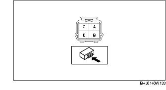
A/F Sensor Heater Resistance Inspection
1. Disconnect the A/F sensor connector.
2. Measure the resistance between A/F sensor terminals C and D.
-
• If not within the specification, replace the A/F sensor. (See AIR FUEL RATIO (A/F) SENSOR REMOVAL/INSTALLATION.)
A/F sensor heater resistance
-
2.16-2.90 ohms [20 °C {68 °F}]
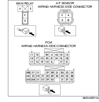
Circuit Open/Short Inspection
1. Disconnect the PCM connector.
2. Disconnect the A/F sensor connector.
3. Inspect the following wiring harnesses for open or short circuit. (Continuity inspection)
Open circuit
-
• If there is no continuity in the following wiring harnesses, there is an open circuit. Repair or replace the wiring harness.
-
- A/F sensor terminal A and PCM terminal 2B
-
- A/F sensor terminal B and PCM terminal 2C
-
- A/F sensor terminal C and main relay terminal C
-
- A/F sensor terminal D and PCM terminal 1V
Short circuit
-
• If there is continuity in the following wiring harnesses, there is a short circuit. Repair or replace the wiring harness.
-
- A/F sensor terminal A and body ground
-
- A/F sensor terminal A and power supply
-
- A/F sensor terminal B and body ground
-
- A/F sensor terminal B and power supply
-
- A/F sensor terminal D and body ground