 |
ar8wzw00001530
FRONT UPPER ARM REMOVAL/INSTALLATION
id021300801900
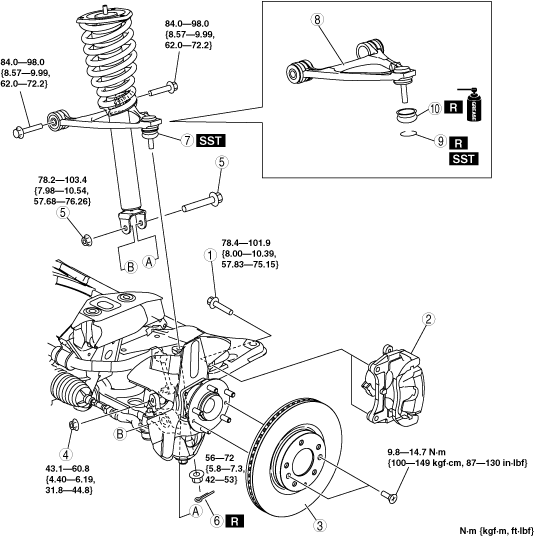
1. Remove in the order indicated in the table.
2. Install in the reverse order of removal.
3. Inspect the front wheel alignment.
(See FRONT WHEEL ALIGNMENT.)
ar8wzw00001530
|
|
1
|
Bolt
|
|
2
|
Caliper and mounting support
|
|
3
|
Disc plate
|
|
4
|
Stabilizer control link nut
|
|
5
|
Shock absorber lower bolt and nut
|
|
6
|
Split pin
(See Split Pin Installation Note.)
|
|
7
|
Front upper arm ball joint
|
|
8
|
Front upper arm
(See Front Upper Arm Removal Note.)
|
|
9
|
Clip
(See Clip Installation Note.)
|
|
10
|
Dust boot
|
Caliper and Mounting Support Removal Note
1. Remove the caliper and mounting support from the steering knuckle and suspend it with a cable in a location out of the way.
Shock Absorber Lower Bolt and Nut Removal Note
1. Loosen the shock absorber upper nuts.
2. Remove the front shock absorber lower bolt and nut.
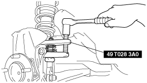
Front Upper Arm Ball Joint Removal Note
1. Remove the front upper arm ball joint from the steering knuckle using the SST.
ar8wzw00001531
|
Front Upper Arm Removal Note
1. Remove the front upper arm bolts.
2. Push down the front lower arm, and then remove the front upper arm from the gap between the shock absorber lower end and the front lower arm.
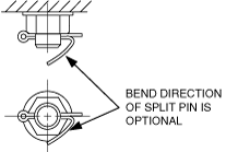
Split Pin Installation Note
1. Install the split pin as shown in the figure.
ar8wzw00001532
|
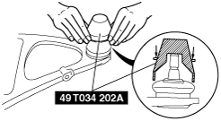
Clip Installation Note
1. Wipe the grease off the ball joint stud.
2. Fill the inside of the new dust boot with grease.
3. Install the dust boot on the ball joint.
4. Install the clip using the SST.
ar8wzw00001533
|
5. Verify that the clip is installed securely to the groove.
6. Wipe off any excess grease.