SHIFT CONTROL STRUCTURE
id051300220200
Features
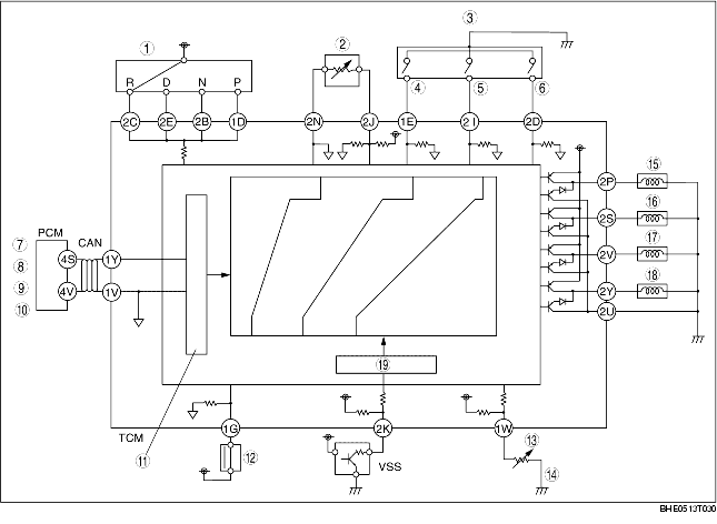
• The TCM selects and determines the shift diagram based on the results of the range and driving mode judgements. Then, based on the shift diagram, the TCM sends signals to the duty-cycle type solenoid valves and the ON/OFF type solenoid valves, according to the VSS and the throttle opening signals, to perform shifting.
Structure
System diagram
|
1
|
TR switch
|
|
2
|
TFT sensor
|
|
3
|
Selector lever component
|
|
4
|
M range switch
|
|
5
|
Up switch
|
|
6
|
Down switch
|
|
7
|
Throttle opening signal
|
|
8
|
Engine torque signal
|
|
9
|
Cruise control signal
|
|
10
|
Engine coolant temperature signal
|
|
11
|
Throttle opening angle
|
|
12
|
Brake switch
|
|
13
|
Up/down signal
|
|
14
|
Steering shift switch
|
|
15
|
Shift solenoid F
|
|
16
|
Shift solenoid B
|
|
17
|
Shift solenoid C
|
|
18
|
Shift solenoid A
|
|
19
|
Vehicle speed
|