 |
bhe0740w005
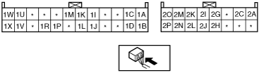
A/C AMPLIFIER INSPECTION [FULL-AUTO AIR CONDITIONER]
id0740008302a1
1. Turn the ignition switch to the ON position.
2. Connect the negative (-) lead of the tester to body ground.
3. By inserting the positive (+) lead of the tester into each A/C amplifier terminal, measure the voltage according to the terminal voltage table.
Terminal Voltage Table (Reference)
bhe0740w005
|
|
Terminal |
Signal name |
Connected to |
Measurement condition |
Voltage (V) |
Inspection item(s) |
|---|---|---|---|---|---|
|
1A
|
Blower fan speed control
|
Power transistor
|
Fan stopped
|
1.0 or less
|
• A/C amplifier: terminal voltage (1A)
|
|
Fan: manual LO
|
2.1
|
||||
|
Fan: manual HI
|
2.9
|
||||
|
1B
|
Blower motor feedback
|
• Blower motor
• Power transistor
|
Fan stopped
|
B+
|
1. Wiring harness: continuity, short circuit (A/C amplifier—power transistor: 1A—D, 1B—C) (Blower motor—blower relay: A—D) (Blower relay—fuse: C—HEATER 40 A, A—A/C 7.5 A)
2. Wiring harness: continuity (Power transistor—body ground: A—GND) (Blower relay—A/C amplifier: E—1L)
3. Power transistor
4. Blower motor
5. Blower relay
6. A/C 7.5 A fuse
7. HEATER 40 A fuse
8. Power transistor replacement
|
|
Fan: manual LO
|
9.0
|
||||
|
Fan: manual HI
|
0.7
|
||||
|
1C
|
Version signal (U.K. specs.)
|
Body ground
|
Under any condition
|
1.0 or less
|
• Wiring harness: continuity (A/C amplifier—GND: 1C—GND)
|
|
1D
|
Version signal (European (L.H.D.) specs.)
|
Body ground
|
Under any condition
|
1.0 or less
|
• Wiring harness: continuity (A/C amplifier—GND: 1D—GND)
|
|
1E
|
—
|
—
|
—
|
—
|
—
|
|
1F
|
—
|
—
|
—
|
—
|
—
|
|
1G
|
—
|
—
|
—
|
—
|
—
|
|
1H
|
—
|
—
|
—
|
—
|
—
|
|
1I
|
Motor operation
|
Air intake actuator
|
Switched to RECIRCULATE
|
1.0 or less
|
• Wiring harness: continuity, short circuit (A/C amplifier—air intake actuator: 1I—A, 1J—C)
• Air intake actuator
|
|
Switched to FRESH
|
12
|
||||
|
1J
|
Motor operation
|
Air intake actuator
|
Switched to RECIRCULATE
|
12
|
• Wiring harness: continuity, short circuit (A/C amplifier—air intake actuator: 1J—C, 1I—A)
• Air intake actuator
|
|
Switched to FRESH
|
1.0 or less
|
||||
|
1K
|
Rear window defroster operation
|
Rear window defroster relay
|
Rear window defroster switch OFF
|
B+
|
• Wiring harness: continuity, short circuit (A/C amplifier—rear window defroster relay: 1K—E)
• Rear window defroster relay
|
|
Rear window defroster switch ON
|
1.0 or less
|
• A/C amplifier: terminal voltage (2C, 2N)
|
|||
|
1L
|
Blower motor operation
|
Blower relay
|
Fan switch OFF
|
B+
|
• Wiring harness: continuity, short circuit (A/C amplifier—blower relay: 1L—E)
• Blower relay
|
|
Fan switch ON
|
1.0 or less
|
• A/C amplifier: terminal voltage (2C, 2N)
|
|||
|
1M
|
A/C
|
Refrigerant pressure switch
|
Fan stopped
|
B+
|
• Wiring harness: continuity, short circuit (A/C amplifier—refrigerant pressure switch: 1M—B) (Refrigerant pressure switch—PCM: C—4W)
• Refrigerant pressure switch
• PCM: terminal voltage (4W)
|
|
Fan switch: ON and A/C switch: ON
|
1.0 or less
|
• A/C amplifier: terminal voltage (2C, 2N)
|
|||
|
1N
|
—
|
—
|
—
|
—
|
—
|
|
1O
|
—
|
—
|
—
|
—
|
—
|
|
1P
|
Serial signal
|
Climate control unit
|
Terminal used for communication therefore determination based on terminal voltage inspection not possible. Only inspect for an open or short circuit in wiring harness between A/C amplifier terminal 1P and climate control unit terminal I.
|
—
|
• Related wiring harness
|
|
1Q
|
—
|
—
|
—
|
—
|
—
|
|
1R
|
Serial signal
|
Climate control unit
|
Terminal used for communication therefore determination based on terminal voltage inspection not possible. Only inspect for an open or short circuit in wiring harness between A/C amplifier terminal 1R and climate control unit terminal J.
|
—
|
• Related wiring harness
|
|
1S
|
—
|
—
|
—
|
—
|
—
|
|
1T
|
—
|
—
|
—
|
—
|
—
|
|
1U
|
Motor operation
|
Air mix actuator
|
Moving towards COLD
|
1.0 or less
|
• Wiring harness: continuity, short circuit (A/C amplifier—air mix actuator: 1U—F (L.H.D.) G (R.H.D.), 1V—G (L.H.D.) F (R.H.D.))
• Air mix actuator
|
|
Moving towards HOT
|
12
|
||||
|
1V
|
Motor operation
|
Air mix actuator
|
Moving towards COLD
|
12
|
• Wiring harness: continuity, short circuit (A/C amplifier—air mix actuator: 1U—F (L.H.D.) G (R.H.D.), 1V—G (L.H.D.) F (R.H.D.))
• Air mix actuator
|
|
Moving towards HOT
|
1.0 or less
|
||||
|
1W
|
Motor operation
|
Airflow mode actuator
|
Switched to DEFROSTER
|
12
|
• Wiring harness: continuity, short circuit (A/C amplifier—airflow mode actuator: 1W—G, 1X—F)
• Airflow mode actuator
|
|
Switched to VENT
|
1.0 or less
|
||||
|
1X
|
Motor operation
|
Airflow mode actuator
|
Switched to DEFROSTER
|
1.0 or less
|
• Wiring harness: continuity, short circuit (A/C amplifier—airflow mode actuator: 1W—G, 1X—F)
• Airflow mode actuator
|
|
Switched to VENT
|
12
|
||||
|
2A
|
B+
|
ROOM 15 A fuse
|
Under any condition
|
B+
|
• Wiring harness: continuity, short circuit (A/C amplifier— fuse: 2F—ROOM 15 A)
• ROOM 15 A fuse
|
|
2B
|
—
|
—
|
—
|
—
|
—
|
|
2C
|
IG2
|
A/C 7.5 A fuse
|
IG SW ON
|
B+
|
• Wiring harness: continuity, short circuit (A/C amplifier— fuse: 2C—A/C 7.5 A)
• A/C 7.5 A fuse
|
|
IG SW LOCK
|
1.0 or less
|
• Wiring harness: continuity, short circuit (A/C amplifier— fuse: 2C—A/C 7.5 A)
|
|||
|
2D
|
—
|
—
|
—
|
—
|
—
|
|
2E
|
—
|
—
|
—
|
—
|
—
|
|
2F
|
—
|
—
|
—
|
—
|
—
|
|
2G
|
Potentiometer input
|
Airflow mode actuator
|
VENT
|
4.0
|
• Wiring harness: continuity, short circuit (A/C amplifier—airflow mode actuator: 2G—E, 2P—C)
• Airflow mode actuator
• A/C amplifier: terminal voltage (2O)
|
|
BILEVEL
|
3.3
|
||||
|
HEAT
|
2.6
|
||||
|
HEAT/DEF
|
1.8
|
||||
|
DEFROSTER
|
1.0
|
||||
|
2H
|
Potentiometer input
|
Air mix actuator
|
Set temperature at MAX COLD
|
3.9
|
• Wiring harness: continuity, short circuit (A/C amplifier—air mix actuator: 2H—E, 2P—A (L.H.D.) C (R.H.D.))
• Air mix actuator
• A/C amplifier: terminal voltage (2O)
|
|
Set temperature at MAX HOT
|
1.1
|
||||
|
2I
|
Solar radiation sensor input
|
Solar radiation sensor
|
Incandescent light (approx. 60 W) shined directly on the solar radiation sensor from a distance of approx. 100 mm {3.9 in}
|
4.0
|
• Wiring harness: continuity (A/C amplifier—solar radiation sensor: 2I—B, 2O—A)
• A/C amplifier: terminal voltage (2O)
• Solar radiation sensor
|
|
Blocking light to solar radiation sensor
|
1.0 or less
|
||||
|
2J
|
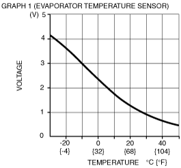
Evaporator temperature sensor input
|
Evaporator temperature sensor
|
Compared with temperature detected by evaporator temperature sensor
|
Refer to graph 1
|
• Wiring harness: continuity (A/C amplifier—evaporator temperature sensor: 2J—B, 2P—A)
• Wiring harness: short circuit (A/C amplifier—evaporator temperature sensor: 2J—B)
• Evaporator temperature sensor
• A/C amplifier: terminal voltage (2C, 2N)
|
|
2K
|
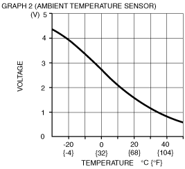
Ambient temperature sensor input
|
Ambient temperature sensor
|
Compared with temperature detected by ambient temperature sensor
|
Refer to graph 2
|
• Wiring harness: continuity (A/C amplifier—ambient temperature sensor: 2K—B, 2P—A)
• Wiring harness: short circuit (A/C amplifier—ambient temperature sensor: 2K—B)
• Ambient temperature sensor
• A/C amplifier: terminal voltage (2C, 2N)
|
|
2 L
|
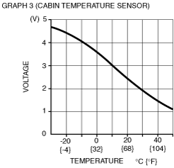
Cabin temperature sensor input
|
Cabin temperature sensor
|
Compared with temperature detected by cabin temperature sensor
|
Refer to graph 3
|
• Wiring harness: continuity (A/C amplifier—cabin temperature sensor: 2L—B, 2P—A)
• Wiring harness: short circuit (A/C amplifier—cabin temperature sensor: 2L—B)
• Cabin temperature sensor
• A/C amplifier: terminal voltage (2C, 2N)
|
|
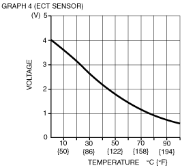
2M
|
ECT sensor input
|
PCM
|
Compared with temperature detected by ECT sensor
|
Refer to graph 4
|
• Wiring harness: continuity, short circuit (A/C amplifier—PCM: 2M—5W)
• ECT sensor
• A/C amplifier: terminal voltage (2C, 2N)
|
|
2N
|
GND
|
Body ground
|
Under any condition
|
1.0 or less
|
• Wiring harness: continuity (A/C amplifier—GND: 2N—GND)
|
|
2O
|
+5 V
|
• Air mix actuator
• Airflow mode actuator
• Solar radiation sensor
|
IG SW ON
|
5.0
|
• Wiring harness: short circuit (A/C amplifier—air mix actuator, airflow mode actuator, solar radiation sensor: 2O—C (L.H.D.) A (R.H.D.), A, A)
• Air mix actuator
• Airflow mode actuator
• Solar radiation sensor
• A/C amplifier: terminal voltage (2C, 2N)
|
|
IG SW LOCK
|
1.0 or less
|
• A/C amplifier replacement
|
|||
|
2P
|
Sensor GND
|
• Ambient temperature sensor
• Cabin temperature sensor
• Evaporator temperature sensor
• Air mix actuator
• Airflow mode actuator
|
Under any condition
|
1.0 or less
|
• A/C amplifier: terminal voltage (2N)
|
 |
 |
 |
 |