DTC B1884, B1890


id080200801600

DTC

B1884

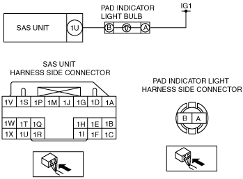
Passenger air bag deactivation (PAD) indicator circuit open or short to body ground

B1890

Passenger air bag deactivation (PAD) indicator circuit short to power supply

DETECTION CONDITION
Warning
•  Detection conditions are for understanding the DTC outline before performing an inspection. Performing an inspection according to only the detection conditions may cause injury due to an operating error, or damage the system. When performing an inspection, always follow the inspection procedure.
•  Malfunction in PAD indicator circuit
POSSIBLE CAUSE
•  Battery malfunction
•  PAD indicator bulb connector malfunction
•  Open circuit in wiring harness between battery and PAD indicator
•  A non-standard PAD indicator bulb is installed
•  PAD indicator bulb malfunction
•  Open or short circuit in wiring harness between PAD indicator and SAS unit
•  SAS unit malfunction

Diagnostic procedure

STEP

INSPECTION

ACTION

1
INSPECT BATTERY
•  Measure the battery positive voltage.
•  Is the voltage 9 V―16 V?
Yes
Go to the next step.
No
Battery is malfunctioning
Inspect the charge/discharge system.
2
INSPECT PAD INDICATOR LIGHT BULB CONNECTOR
Warning
•  Handling the air bag system components improperly can accidentally deploy the air bag modules and pre-tensioner seat belts, which may seriously injure you. Read the air bag system service warnings and cautions before handling the air bag system components.
•  Remove the PAD indicator light bulb.
•  Inspect the PAD indicator light bulb connector. (Corrosion, damage, and disconnected pins)
•  Is there any malfunction of the PAD indicator light bulb connector?
Yes
Go to the next step.
No
Repair the PAD indicator light bulb wiring harness.
3
INSPECT PAD INDICATOR LIGHT BULB
•  Verify the PAD indicator light bulb capacity (W).
•  Has a PAD indicator light bulb with a bulb capacity (W) that is the same as a standard product been installed?
Yes
Go to the next step.
No
Replace the bulb with a standard capacity (W) PAD indicator light bulb.
After replacement, go to Step 8.
4
INSPECT WIRING HARNESS BETWEEN BATTERY AND PAD INDICATOR LIGHT BULB
•  Connect the negative battery cable.
•  Turn the ignition switch to the ON position.
•  Measure the PAD indicator light bulb connector terminal A voltage.
Note
•  Measure the voltage while shaking the wiring harness between the battery and the PAD indicator light bulb.
•  Is the voltage 9 V or more?
Yes
Go to the next step.
No
Repair the wiring harness between the battery and PAD indicator light bulb.
5
INSPECT PAD INDICATOR
•  Ground PAD indicator connector terminal B using a jumper wire.
•  Turn the ignition switch to the ON position.
•  Does the PAD indicator illuminate?
Yes
Go to the next step.
No
Replace the PAD indicator light bulb.
6
INSPECT WIRING HARNESS BETWEEN PAD INDICATOR LIGHT BULB AND SAS UNIT
•  Turn the ignition switch to the LOCK position.
•  Disconnect the negative battery cable and wait for 1 min or more.
•  Remove the column cover. (See COLUMN COVER REMOVAL/INSTALLATION.)
•  Disconnect the clock spring connector.
•  Remove the glove compartment. (See GLOVE COMPARTMENT REMOVAL/INSTALLATION.)
•  Disconnect the passenger-side air bag module connector.
•  Disconnect the driver and passenger-side side air bag module connectors.
•  Disconnect the driver and passenger-side curtain air bag module connector.
•  Remove the rear door lower trim. (See REAR DOOR LOWER TRIM REMOVAL/INSTALLATION.)
•  Disconnect the driver and passenger-side pre-tensioner seat belt connectors.
•  Partially peel back the floor covering.
•  Disconnect the SAS unit connector.
•  Inspect the wiring harness between PAD indicator light bulb connector terminal B and SAS unit connector terminal 1U for the following:
―  Short circuit between terminals
―  Short to body ground
―  Open circuit
Note
•  Inspect for continuity while shaking the wiring harness between the SAS unit and PAD indicator light bulb.
•  Is the wiring harness normal?
Yes
Go to the next step.
No
Repair the wiring harness between the PAD indicator light bulb and SAS unit.
7
INSPECT THE WIRING HARNESS BETWEEN SAS UNIT AND PAD INDICATOR LIGHT BULB FOR A SHORT CIRCUIT TO THE POWER SUPPLY
•  Connect the negative battery cable.
•  Turn the ignition switch to the ON position.
•  Measure the voltage of SAS unit connector terminal 1U.
Note
•  Measure the voltage while shaking the wiring harness between the SAS unit and PAD indicator light bulb.
•  Is the voltage measured?
Yes
Repair the wiring harness between the PAD indicator light bulb and SAS unit.
No
Go to the next step.
8
PERFORM SAS UNIT DTC INSPECTION
•  Turn the ignition switch to the LOCK position.
•  Disconnect the negative battery cable and wait for 1min or more.
•  Reconnect all disconnected connectors.
•  Connect the negative battery cable.
•  Turn the ignition switch to the ON position.
•  Clear the DTC for the SAS unit using the WDS or eguivalent.
•  Perform the DTC inspection for the SAS unit using the WDS or eguivalent.
•  Are the same DTCs present?
Yes
Replace the SAS unit.
No
DTC troubleshooting completed.