• Refer to RX-8 Workshop Manual.
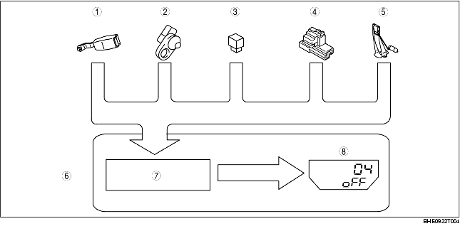
• When the parts listed in the chart are operated and output a signal to the instrument cluster, the built in microcomputer judges the quality of the input circuit based on that signal.
|
Check code
|
Parts sending input signal
|
|---|---|
|
01
|
Buckle switch
|
|
04
|
Door switch
|
|
08
|
TNS relay
|
|
22
|
Fuel gauge sender unit
|
|
31
|
Key reminder switch
|
|
55
|
Dimmer switch
|
|
1
|
Buckle switch
|
|
2
|
Door switch
|
|
3
|
TNS relay
|
|
4
|
Key reminder switch
|
|
5
|
Fuel gauge sender unit
|
|
6
|
Instrument cluster
|
|
7
|
Microcomputer
|
|
8
|
LCD
|
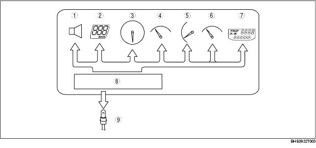
• By operating the parts listed in the chart, the built in microcomputer judges the quality of the individual parts.
|
1
|
Buzzer
|
|
2
|
Speedometer
|
|
3
|
Tachometer
|
|
4
|
Water temperatuer gauge
|
|
5
|
Fuel gauge
|
|
6
|
Oil pressure gauge
|
|
7
|
LCD
|
|
8
|
Microcomputer
|
|
9
|
Ignition key illumination
|
• The PID/data monitoring items for the instrument cluster is as shown in the table below.
Monitor item table