1. Inspect the speedometer by setting it to check code 12 of the input/output check mode.(See INSTRUMENT CLUSTER INPUT/OUTPUT CHECK MODE.)
1. Adjust the tire pressure to the specification.
2. Using a speedometer tester, verify that the tester reading is as indicated in the table below.
|
Speedometer tester indication (km/h)
|
Allowable range (km/h)
|
|---|---|
|
20
|
20-23
|
|
40
|
40-43
|
|
60
|
60-63
|
|
80
|
80-83
|
|
100
|
100-103
|
|
120
|
120-123
|
|
140
|
140-143
|
|
Speedometer tester indication (mph)
|
Allowable range (mph)
|
|---|---|
|
10
|
10-13
|
|
20
|
20-23
|
|
30
|
30-33
|
|
40
|
40-43
|
|
50
|
50-53
|
|
70
|
70-73
|
|
80
|
80-83
|
3. Verify that the speedometer reading is within the range indicated in the table.
1. Inspect the tachometer by setting it to check code 13 of the input/output check mode.(See INSTRUMENT CLUSTER INPUT/OUTPUT CHECK MODE.)
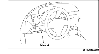
1. Connect the WDS or external diagnostic equipment to the diagnostic connector 2 (16-pin).
2. Compare the data monitor item (RPM) with the tachometer indication.
1. Inspect the fuel gauge by setting it to check code 23 of the input/output check mode.(See INSTRUMENT CLUSTER INPUT/OUTPUT CHECK MODE.)
1. Inspect the water temperature gauge by setting it to check code 25 of the input/output check mode.(See INSTRUMENT CLUSTER INPUT/OUTPUT CHECK MODE.)
1. Inspect the oil pressure gauge by setting it to check code 28 of the input/output check mode.(See INSTRUMENT CLUSTER INPUT/OUTPUT CHECK MODE.)