AUTOMATIC TRANSAXLE DISASSEMBLY
BUE051700000108
Before Service Precaution
-
• Disassemble the transaxle in a clean area (dustproof work space) to prevent entry of dust into the mechanisms.
-
• To ensure that all foreign particles stay in the oil pan, make sure that the transaxle is never tipped completely over while the oil pan is still installed.
-
• Sufficiently examine the foreign material which was identified in the oil pan and on the magnet, and judge the transaxle condition.
-
• Disassembly work should be conducted by bare hands or use of vinyl gloves. Do not use gloves and clean rag to prevent the entry of waste thread.
-
• Use only plastic hammers when applying force to separate the light alloy case joints.
-
• Several parts resemble one another; arrange them so that they do not get mixed up.
-
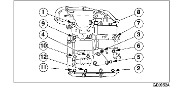
Warning
-
• Although the stand has a self-locking brake system, there is a possibility that the brake may not hold when the transaxle is held in a lopsided position on the stand. This would cause the transaxle to turn suddenly, causing serious injury. Never keep the transaxle tilted to one side. Always hold the rotating handle firmly when turning the transaxle.
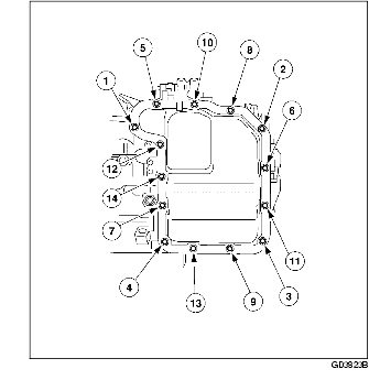
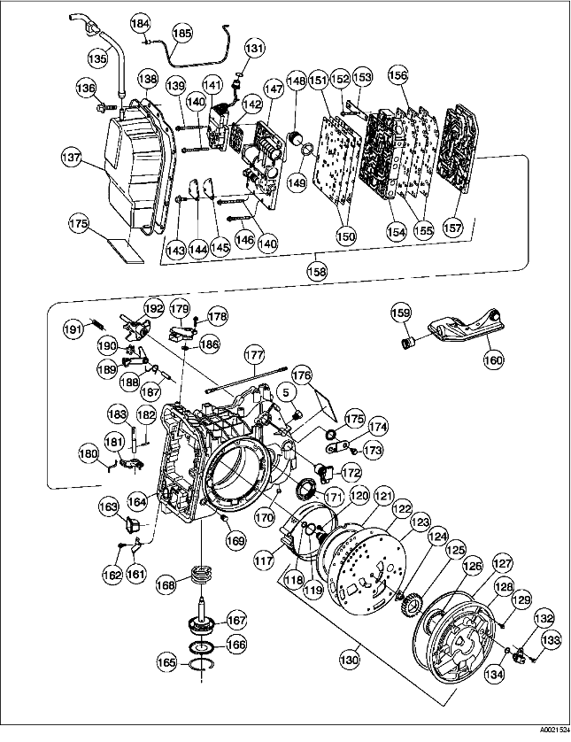
Component Part

.
|
1
|
Converter component
|
|
2
|
Seal component (Converter impeller hub)
|
|
3
|
Bolt (Pan torx head)
|
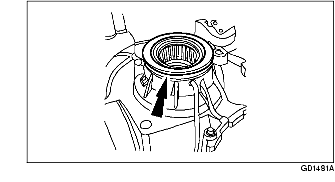
|
4
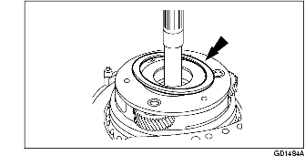
|
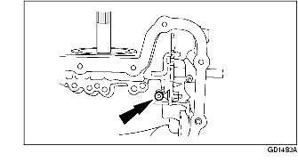
Stator support component
|
|
5
|
Pipe plug (Dry seal)
|
|
6
|
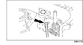
Connector component (Cooler line fitting)
|
|
7
|
Bolt (Attaches case to converter housing)
|
|
8
|
Converter housing component
|
|
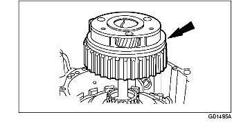
9
|
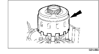
Converter housing (Case)
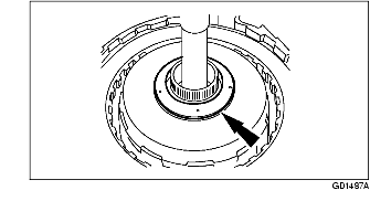
|
|
10
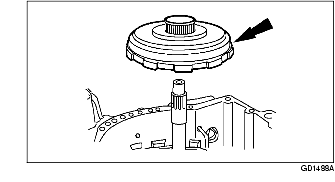
|
Tube component (Differential lube)
|
|
11
|
Bolt
|
|
12
|
Gasket (Transaxle split flange)
|
|
13
|
Dipstick
|
|
14
|
Bolt (Fluid filler tube)
|
|
15
|
Fluid filler tube
|
|
16
|
Grommet
|
|
17
|
Final drive gear
|
|
18
|
Retaining ring (Final drive)
|
|
19
|
Bearing (No. 15)
(Differential carrier)
|
|
20
|
Shim (Selective fit No. 14)
(Differential bearing)
|
|
21
|
Differential gear case component
|
|
22
|
Washer (Rear axle differential pinion)
|
|
23
|
Differential pinion gear
|
|
24
|
Thrust washer (Differential side gear)
|
|
25
|
Differential side gear
|
|
26
|
Differential pinion shaft
|
|
27
|
Coil spring pin (Attaches differential pinion shaft)
|
|
28
|
Needle bearing (Final drive planet gear)
|
|
29
|
Spacer (Final drive planet gear)
|
|
30
|
Final drive planet gear
|
|
31
|
Washer (Final drive planet gear)
|
|
32
|
Final drive pinion shaft
|
|
33
|
Retaining ring (77.3 External)
|
|
34
|
Planet and carrier component (Final drive)
|
|
35
|
Pan (Chain cover)
|
|
36
|
Drive chain component
|
|
37
|
Driven sprocket component
|
|
38
|
Pan (Chain cover)
|
|
39
|
Magnet
|
|
40
|
Pan component (Chain cover)
|
|
41
|
Bearing component No. 13
(Driven sprocket)
|
|
42
|
Outer bearing component (No. 12)
(Driven sprocket)
|
|
43
|
Shim (driven sprocket)
(selective fit No. 11)
|
|
44
|
Inner bearing component (No. 12)
(Driven sprocket)
|
|
45
|
Thrust washer (selective fit No. 10)
(Drive sprocket)
|
|
46
|
Bearing component (No. 17)
(Stator support)
|
|
47
|
Overdrive reverse ring gear component
|
|
48
|
Drive sprocket bearing component
(Overdrive Reverse Ring Gear)
|
|
49
|
Thrust bearing component
(Reverse overdrive ring gear)
|
|
50
|
Planet component (No. 8)
(Overdrive reverse)
|
|
51
|
Retaining ring (Low one-way clutch)
|
|
52
|
Low one-way clutch plate
|
|
53
|
Low one-way clutch component
|
|
54
|
wave spring (Low/reverse clutch)
|
|
55
|
Pressure plate (Low/reverse clutch)
|
|
56
|
Drive plate (Low/reverse clutch)
|
|
57
|
Driven plate (Low/reverse clutch)
|
|
58
|
Retaining ring (Low/reverse clutch return spring)
|
|
59
|
Return spring component (Low/reverse clutch)
|
|
60
|
Low/reverse clutch piston outer seal (Large)
|
|
61
|
Low/reverse clutch piston
|
|
62
|
Low/reverse clutch piston inner seal (Small)
|
|
63
|
Sun gear component (Overdrive/reverse)
|
|
64
|
Thrust bearing component (No. 7)
(Reverse/overdrive sun gear)
|
|
65
|
Ring gear component (Low/intermediate)
|
|
66
|
Thrust bearing component (Outer No. 6)
(Low/intermediate carrier)
|
|
67
|
Planet component (Low/intermediate)
|
|
68
|
Thrust bearing component (Inner No. 5)
(Low/reverse sun gear)
|

.
|
69
|
Sun gear, race, and bushing component
(Low/intermediate)
|
|
70
|
Retaining ring (Forward one-way clutch and reverse clutch spring)
|
|
71
|
Retainer (Forward one-way clutch)
|
|
72
|
Outer race (Forward one-way clutch)
|
|
73
|
Forward one-way clutch
|
|
74
|
Coast clutch hub
|
|
75
|
Retaining ring (Coast clutch hub)
|
|
76
|
Forward one-way Clutch and sun gear component
|
|
77
|
Thrust bearing component (No. 4)
(Turbine shaft)
|
|
78
|
Turbine shaft
|
|
79
|
Seal (Forward/direct clutch hub)
|
|
80
|
Retaining ring (Forward/direct clutch plate)
|
|
81
|
Pressure plate (Forward clutch)
|
|
82
|
Driven plate (Forward clutch)
|
|
83
|
Drive plate (Forward clutch)
|
|
84
|
Wave spring (Forward clutch)
|
|
85
|
Pressure plate (Coast clutch)
|
|
86
|
Driven plate (Coast clutch)
|
|
87
|
Drive plate (Coast clutch)
|
|
88
|
Retaining ring (Forward clutch spring)
|
|
89
|
Return spring component (Forward coast clutch)
|
|
90
|
Piston and seal component
|
|
91
|
Outer lip Seal (Forward clutch piston)
|
|
92
|
Piston component (Forward clutch)
|
|
93
|
Inner lip Seal (Forward clutch piston)
|
|
94
|
Cylinder component (Forward/direct/coast clutch)
|
|
95
|
Outer lip Seal (Direct clutch piston)
|
|
96
|
Piston and seal component (Direct clutch)
|
|
97
|
Inner lip Seal (Direct clutch piston)
|
|
98
|
Return spring component (Direct clutch)
|
|
99
|
Retaining ring (Direct clutch spring)
|
|
100
|
Seal (Direct clutch cylinder)
|
|
101
|
Washer (Direct clutch thrust)
|
|
102
|
Driven plate (Direct clutch)
|
|
103
|
Drive plate (Direct clutch)
|
|
104
|
Pressure plate (Direct clutch)
|
|
105
|
Shell component (Direct clutch)
|
|
106
|
Drum component (Reverse clutch)
|
|
107
|
Piston component (Reverse clutch)
|
|
108
|
Return spring component (Reverse clutch)
|
|
109
|
Driven plate (Reverse input clutch)
|
|
110
|
Drive plate (Reverse input clutch)
|
|
111
|
Pressure plate (Reverse input clutch)
|
|
112
|
Retaining ring (selective fit)
(Reverse clutch)
|
|
113
|
Reverse clutch hub
|
|
114
|
Retaining ring (Reverse clutch hub)
|
|
115
|
Thrust bearing component (No. 1)
(Pump support)
|
|
116
|
Shaft (Pump drive)
|
.
|
117
|
Band component (Intermediate/overdrive)
|
|
118
|
Seal (Multiple clutch cooling)
|
|
119
|
Inner seal (Pump support clutch)
|
|
120
|
Bolt (Attaches pump support to pump body)
|
|
121
|
Pump support
|
|
122
|
Gasket (Pump body separator)
|
|
123
|
Plate (Pump body separator)
|
|
124
|
Insert (Pump drive gear)
|
|
125
|
Pump drive gear
|
|
126
|
Pump driven gear
|
|
127
|
Seal
|
|
128
|
Front pump body
|
|
129
|
Bolt
|
|
130
|
Pump component (Front)
|
|
131
|
O-ring (Solenoid valve body)
|
|
132
|
Transaxle turbine shaft speed (TSS) sensor component
|
|
133
|
Bolt
|
|
134
|
O-ring
|
|
135
|
Vent component (Main control cover)
|
|
136
|
Bolt (Main control cover)
|
|
137
|
Main control cover
|
|
138
|
Gasket
|
|
139
|
Bolt
|
|
140
|
Bolt
|
|
141
|
Transaxle control solenoid body
|
|
142
|
Gasket
|
|
143
|
Bolt
|
|
144
|
Plate
|
|
145
|
Gasket
|
|
146
|
Bolt
|
|
147
|
Accumulator body component
|
|
148
|
Plug (2/4 accumulator valve)
|
|
149
|
Seal (2/4 accumulator body)
|
|
150
|
Gasket
|
|
151
|
Plate (Accumulator body separator)
|
|
152
|
Bolt
|
|
153
|
Detent spring component (Manual valve)
|
|
154
|
Body component, main control lower
|
|
155
|
Gasket
|
|
156
|
Plate (Control valve separator)
|
|
157
|
Plate (Case and main control transfer)
|
|
158
|
Main control and pressure tap component
|
|
159
|
Seal (Recirculating regulator exhaust)
|
|
160
|
Fluid filter and seal component
|
|
161
|
Bracket (Thermal valve)
|
|
162
|
Bolt
|
|
163
|
TFT sensor
|
|
164
|
Transaxle case component
|
|
165
|
Ring (Intermediate/overdrive servo cylinder cover)
|
|
166
|
Cover component (Intermediate/overdrive servo)
|
|
167
|
Piston and rod component
(Intermediate/overdrive servo)
|
|
168
|
Return spring component
(Intermediate overdrive servo piston)
|
|
169
|
Plug (Line pressure)
|
|
170
|
Plug (Transaxle drain)
|
|
171
|
Differential oil seal
|
|
172
|
Output shaft speed (OSS) sensor component
|
|
173
|
Bolt
|
|
174
|
Manual control lever component
|
|
175
|
Seal
|
|
176
|
Transaxle identification tag
|
|
177
|
Manual valve detent lever actuating rod component
|
|
178
|
Bolt and washer component
|
|
179
|
TR switch
|
|
180
|
Manual valve actuator rod
|
|
181
|
Manual valve detent inner lever component
|
|
182
|
Retainer pin
|
|
183
|
Inner shaft (Manual valve detent)
|
|
184
|
Seal
|
|
185
|
Tube (Final drive lube)
|
|
186
|
Seal
|
|
187
|
Parking pawl shaft
|
|
188
|
Return spring (Parking pawl)
|
|
189
|
Parking brake pawl component
|
|
190
|
Retainer and bolt component (Parking pawl shaft)
|
|
191
|
Parking pawl ratcheting spring
|
|
192
|
Parking brake lever
|
Bushings, Bearing and Thrust Washer Locator

.
|
1
|
Thrust bearing(No. 5)
(Low/intermediate sun gear)
|
|
2
|
Thrust bearing (No. 6)
(Low/intermediate carrier)
|
|
3
|
Thrust bearing (No. 7)
(Reverse/overdrive sun gear)
|
|
4
|
Thrust bearing (No. 9)
(Reverse/overdrive ring gear)
|
|
5
|
Thrust washer (No.10)
(Drive sprocket)
|
|
6
|
Thrust washer
(Differential side gear)
|
|
7
|
Differential bearing (No. 15)
|
|
8
|
Shim (No. 14)
(Differential bearing)
|
|
9
|
Thrust washer
(Differential pinion)
|
|
10
|
Thrust washer (No. 13)
(Driven sprocket)
|
|
11
|
Bearing (No. 12)
(Driven sprocket)
|
|
12
|
Bearing (No. 18)
(Driven sprocket)
|
|
13
|
Shim (No. 11)
(Driven sprocket)
|
|
14
|
Bearing (No. 17)
(Stator support)
|
|
15
|
Bearing (No. 16)
(Reverse/overdrive ring gear)
|
|
16
|
Thrust washer (No. 2)
(Direct clutch)
|
|
17
|
Thrust bearing (No. 1)
(Pump support)
|
|
18
|
Thrust bearing (No. 4)
(Turbine shaft)
|
Disassembly
1. Inspect transaxle during disassembly.
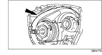
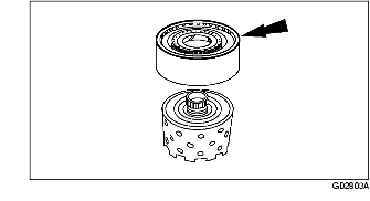
2. Remove the torque converter.
-
Caution
-
• Do not tilt the torque converter when removing it. This can damage the torque converter hub.
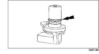
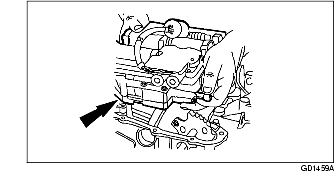
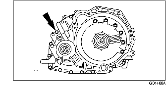
3. Remove the output shaft speed (OSS) sensor.
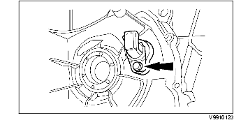
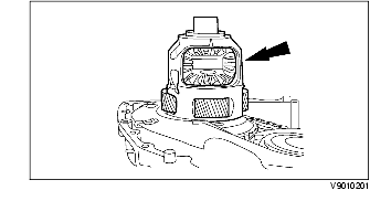
4. Remove the turbine shaft speed (TSS) sensor.
-
(1) Remove the bolt.
-
(2) Remove the TSS sensor.
5. Remove and discard the TSS and OSS sensor O-ring seals.
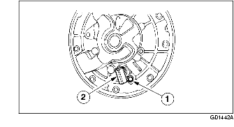
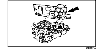
6. Remove the transaxle range (TR) sensor.
-
(1) Remove the bolt.
-
(2) Remove the TR sensor from the manual valve detent lever shaft.
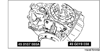
7. Using the SST, secure the transaxle to the bench.
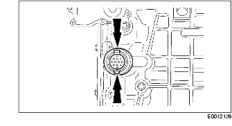
8. Position the drain pan under the transaxle, remove the drain plug, and drain the transaxle fluid.
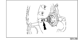
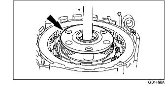
9. Remove the pump component driveshaft.
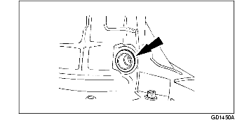
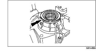
10. Using the SST, remove and discard the torque converter impeller hub seal.
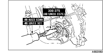
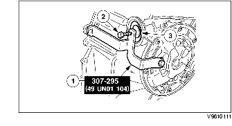
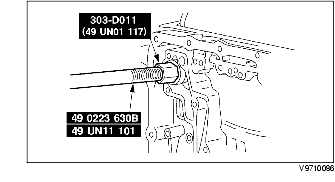
11. Using the SST, remove the left-hand differential seals.
12. Using the SST, remove the right-hand differential seals.
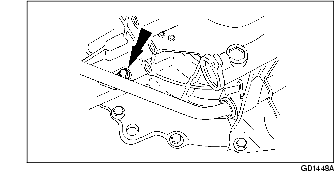
13. Remove the transaxle fluid filler tube bolt.
14. Remove the transaxle fluid filler tube.
15. Remove and discard the transaxle filler tube grommet.
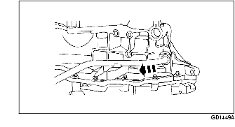
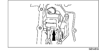
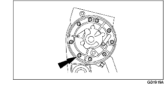
16. Remove the bolts in the indicated sequence.
17. Remove the main control cover bolts, and cover.
18. Remove and discard the gasket.
19. Inspect the fitting of the main control cover vent tube for blockage.
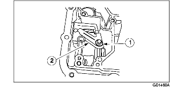
20. Remove the bolts in the indicated sequence.
21. Remove the main control valve body bolts.
22. Disconnect the manual valve link from the manual valve when lifting the main control valve body from the case.
23. Remove the solenoid body electrical connector.
-
Caution
-
• Do not pull on solenoid body electrical connector wires, or use a hammer on the electrical connector.
24. Release the retaining tabs and push the connector through the transaxle case.
25. Support the manual valve and remove the main control.
26. Remove the thermostatic fluid level control valve bracket.
-
(1) Remove the bolt.
-
(2) Remove the bracket.
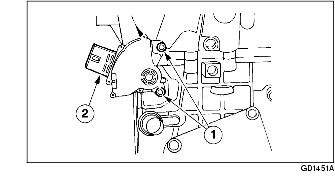
27. Remove the thermostatic fluid level control valve.
28. Remove the forward clutch circuit filter (if equipped).
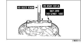
29. Using the SST, remove the servo component.
-
Warning
-
• The servo and servo cover are under high spring force. Use caution when removing servo cover.
-
Caution
-
• Do not use a screwdriver to remove the retaining ring or damage to the case can occur. Use only snap ring pliers to remove the retaining ring.
-
(1) Install the SST.
-
(2) Compress the servo component by tightening the bolt.
-
(3) Remove the retaining ring.
30. Remove the servo cover component.
31. Remove the intermediate and overdrive servo piston and return spring.
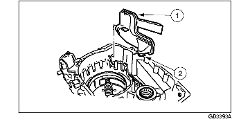
32. Inspect the intermediate and overdrive servo component and bore for damage or wear.
-
Note
-
• If the bonded seal is damaged, install a new servo component.
-
(1) Servo cover with bonded seal.
-
(2) Cushion spring.
-
(3) Servo apply rod.
-
(4) Servo return spring.
-
• Case servo bore.
33. Remove the bolts. (20 bolts)
-
Note
-
• Position the transaxle with the torque converter housing facing upward.
34. Separate the torque converter housing from the transaxle case.
-
Note
-
• Place the torque converter housing on the engine flange side after removal to prevent damage to the lube tube.
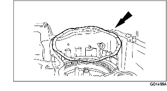
35. Remove and discard the transaxle split flange gasket.
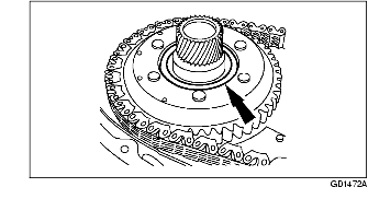
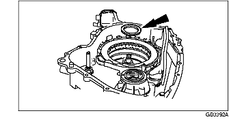
36. Remove the differential bearing and shim.
-
(1) Remove the No. 15 differential bearing.
-
(2) Remove the No. 14 differential bearing shim.
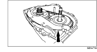
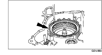
37. Remove the final drive carrier and differential component.
38. Remove the No. 13 driven sprocket thrust bearing.
39. Unclip and remove the chain pan cover.
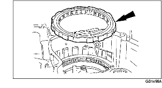
40. Remove the No. 10 driven sprocket thrust washer from the reverse/overdrive ring gear component.
-
Note
-
• The driven sprocket thrust washer may adhere to the converter housing.
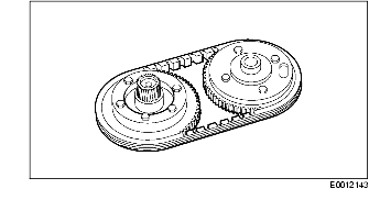
41. Remove the chain drive, reverse/overdrive ring gear, and driven sprocket component.
42. Separate the drive chain component from the driven sprocket component and reverse/overdrive ring gear component.
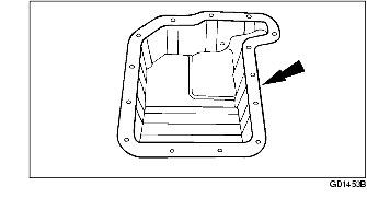
43. Remove the chain pan (with the magnet retained) from the transaxle case.
-
Note
-
• Inspect the magnet located on the chain pan for excessive metal particles.
44. Assemble the SST.
45. Using the SST, remove and discard the fluid filter recirculating regulator exhaust seal.
46. Remove the fluid filter and seal component.
-
(1) Discard the fluid filter.
-
(2) Discard the fluid filter seal.
47. Remove the No. 12 driven sprocket bearing.
48. Remove the No. 11 driven sprocket shim (selective fit).
49. Disconnect the parking lever actuating rod from the parking cam actuator lever component.
50. Disconnect the parking lever actuation rod from the manual valve detent lever, and remove the parking lever actuation rod.
51. Remove the No. 9 reverse/overdrive ring gear thrust bearing.
-
Note
-
• The thrust bearing may adhere to the reverse/overdrive sprocket.
-
• The thrust bearing is part of the reverse/overdrive carrier component.
52. Remove the reverse/overdrive carrier component together with No. 8 thrust bearing.
-
Note
-
• The thrust bearing is part of the reverse/overdrive carrier component.
53. Remove the reverse/overdrive sun gear and shell component.
54. Remove the reverse/overdrive sun gear and No. 7 shell thrust bearing.
-
Note
-
• The thrust bearing may adhere to the reverse/overdrive sun gear and shell.
55. Remove the low/intermediate ring gear component.
56. Remove the No. 6 low/intermediate carrier thrust bearing.
-
Note
-
• The low/intermediate carrier thrust bearing may adhere to the low/intermediate ring gear.
57. Remove the low/intermediate carrier component.
58. Remove the No. 5 low/intermediate sun gear thrust bearing and tag for installation.
59. Remove the forward one-way clutch and low/intermediate sun gear.
60. Remove the No. 4 turbine shaft thrust bearing.
-
Note
-
• The turbine shaft thrust bearing may adhere to the forward one-way clutch and low/intermediate sun gear.
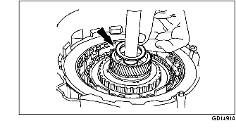
61. Remove the turbine shaft component.
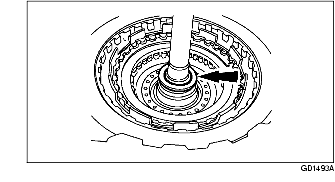
62. Remove the forward/coast/direct clutch cylinder from the reverse clutch drum component.
63. Remove the forward/coast/direct clutch cylinder from the reverse clutch drum component.
64. Remove the No. 1 pump support thrust bearing and tag for installation.
-
Note
-
• The pump support thrust bearing component may adhere to the reverse clutch drum component.
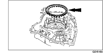
65. Remove the low one-way clutch retaining ring.
66. Remove the low one-way clutch thrust plate.
67. Remove the low one-way clutch component.
-
Note
-
• The low one-way clutch component should be removed as a component.
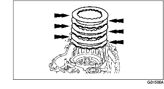
68. Remove the low/reverse clutch wave spring.
69. Remove the low/reverse clutch plates.
-
• Inspect the friction plates for partially stripped, broken or bent spline teeth, burnt, worn or flaked-off friction material, and warped or bent friction discs.
-
• Inspect the steel plates for heat discoloration or warpage.
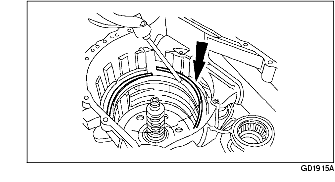
70. Remove the low/reverse clutch return spring retaining ring.
71. Remove the low/reverse clutch return spring component.
72. Remove the low/reverse clutch piston.
-
Note
-
• Rotate the low/reverse clutch piston while pulling upward.
73. Position the transaxle so the pump assembly is facing upward.
74. Remove the pump component bolts.
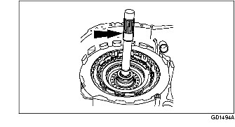
75. Using the SST, remove the pump component.
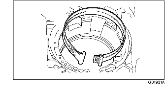
76. Remove the intermediate and overdrive band component from the case.
-
• Inspect the intermediate and overdrive band component for damage and wear.