FORWARD/COAST/DIRECT CLUTCHES REMOVAL/INSTALLATION
BUE051719500103
Removal
.
|
1
|
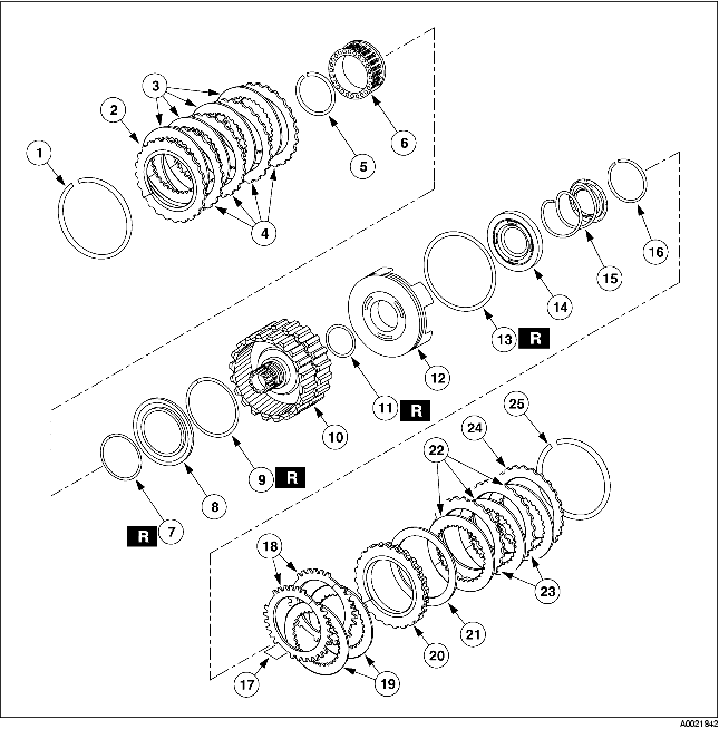
Retaining ring
|
|
2
|
Pressure plate
|
|
3
|
Drive plate
|
|
4
|
Driven plate
|
|
5
|
Retaining ring
|
|
6
|
Return spring
|
|
7
|
Piston inner lip seal
|
|
8
|
Piston component
|
|
9
|
Piston outer lip seal
|
|
10
|
Cylinder component
|
|
11
|
Piston inner lip seal
|
|
12
|
Piston component
|
|
13
|
Piston outer lip seal
|
|
14
|
Piston and seal component
|
|
15
|
Return spring
|
|
16
|
Retaining ring
|
|
17
|
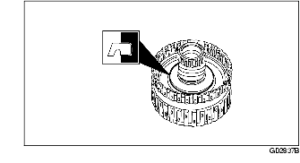
Clearance for fingers on the forward clutch piston
|
|
18
|
Driven plate
|
|
19
|
Drive plate
|
|
20
|
Pressure plate
|
|
21
|
Wave spring
|
|
22
|
Internal spline drive plates
|
|
23
|
External spline driven plates
|
|
24
|
Pressure plate
|
|
25
|
Retaining ring
|
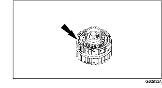
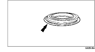
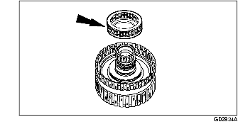
1. Remove the direct clutch pressure plate retaining ring.
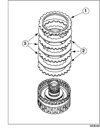
2. Disassemble the direct clutch pack.
-
(1) Remove the direct clutch pressure plate.
-
(2) Remove the direct clutch driven plates.
-
(3) Remove the direct clutch drive plates.
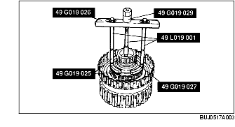
3. Remove the direct clutch spring retaining ring.
-
Warning
-
• Use caution when releasing tool pressure on the clutch piston springs. Failure to follow these instructions can result in personal injury.
-
Caution
-
• Do not compress the direct clutch return springs completely.
-
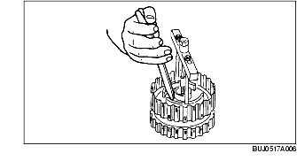
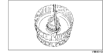
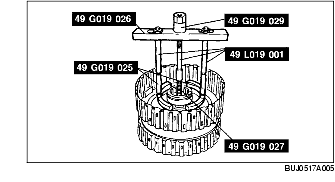
(1) Using the SSTs, compress the direct clutch return springs.
-
(2) Remove the direct clutch return spring retaining ring.
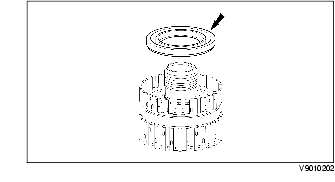
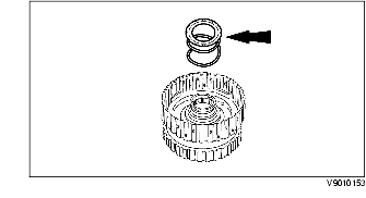
4. Remove the direct clutch return spring component.
5. Remove the direct clutch piston component.
6. Remove and discard the direct clutch piston outer lip seal.
7. Remove and discard the direct clutch piston inner lip seal from the forward/coast/direct clutch cylinder component.
8. Remove the forward clutch pressure plate retaining ring.
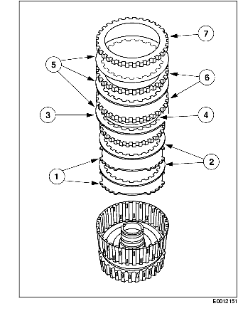
9. Remove the forward and coast clutch plates.
-
(1) Forward clutch pressure plate
-
(2) Forward clutch external spline driven plates
-
(3) Coast clutch internal spline drive plates
-
(4) Coast clutch external spline driven plates
-
(5) Coast clutch pressure plate
-
(6) Forward clutch internal spline drive plates
-
(7) Forward clutch wave spring
10. Remove the forward/coast clutch return spring retaining ring.
-
Warning
-
• Use caution when releasing tool pressure on the clutch piston springs. Failure to follow these instructions can result in personal injury.
-
Caution
-
• Do not compress the return springs completely.
-
(1) Using the SSTs, compress the return spring.
-
(2) Remove the retaining ring.
11. Remove the forward/coast clutch return spring component.
12. Remove the forward and coast clutch pistons.
13. Remove the forward clutch piston inner seal from the forward/coast/direct clutch cylinder component.
14. Remove and discard the forward clutch piston outer lip seal.
15. Separate the coast clutch piston component from the forward clutch piston component.
16. Clean all parts thoroughly in a clean solvent and blow dry with moisture-free regulated compressed air.
-
Warning
-
• Air pressure must not exceed 138 kPa {1.4 kgf/cm2, 20 psi}. Wear safety glasses when using compressed air. Failure to follow these instructions can result in personal injury.
-
Note
-
• Do not clean the clutch plates in a vapor degreaser or in any other type of detergent solution.
-
• Clean the steel clutch plates with a lint-free cloth.
-
• Soak the new clutch plates in the specified transaxle fluid for 30 minutes or more before assembly.
17. Inspect the parts for damage or wear.
-
(1) Spline teeth
-
(2) Clutch plates
-
(3) Seal
-
(4) Bushing
-
(5) Check balls in pistons
-
(6) Piston bore
-
(7) Passages and lubrication holes in the forward/coast/direct clutch cylinder
Installation
1. Soak the internal spline clutch plates in clean ATF or equivalent for 30 minutes or more before assembly.
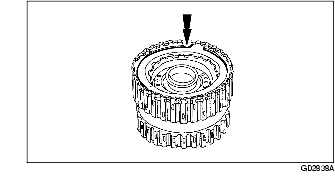
2. Install the new forward clutch piston inner seal on the forward/coast/direct clutch cylinder component.
3. Install the new forward clutch piston outer lip seal on the forward clutch piston component.
4. Install the forward clutch piston assembly in the forward/coast/direct clutch cylinder component.
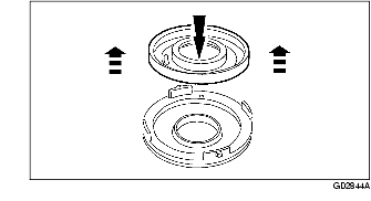
5. Install the coast clutch piston component onto the SST.
6. Using the SST, install the coast clutch piston into the forward clutch piston component.
7. Install the forward/coast clutch return spring component.
8. Install the forward/coast clutch return spring retaining ring.
-
Warning
-
• Use caution when releasing tool pressure on the clutch piston springs. Failure to follow these instructions can result in personal injury.
-
(1) Using the SSTs, compress the return spring.
-
(2) Install the forward/coast clutch retaining ring.
9. Install the forward and coast clutch plates in the sequence shown.
-
(1) Coast clutch external spline driven plates
-
(2) Coast clutch internal spline drive plates
-
(3) Coast clutch pressure plate
-
(4) Forward clutch wave spring
-
(5) Forward clutch internal spline drive plates
-
(6) Forward clutch external spline driven plates
-
(7) Forward clutch pressure plate
10. Install the forward clutch pressure plate retaining ring.
11. Using a feeler gauge, measure the clearance between the forward clutch pressure plate and the forward clutch pressure plate retaining ring.
-
• Take a second measurement on the opposite side.
-
• Average the two measurements to obtain the clearance.
-
• If the clearance is not within specification, select and install the proper thickness retaining ring to obtain the standard clearance.
-
• Retaining ring sizes:
-
• 1.43-1.53 mm {0.056-0.060 in}
-
• 1.59-1.69 mm {0.062-0.066 in}
-
• 1.75-1.85 mm {0.069-0.073 in}
-
• 1.92-2.02 mm {0.075-0.079 in}
12. Install the new direct clutch piston inner lip seal on the direct clutch cylinder component.
13. Install the direct clutch piston outer seal on the direct clutch piston component.
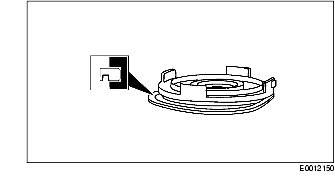
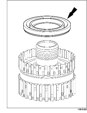
14. Install the direct clutch piston component in the forward/coast/direct clutch cylinder component.
-
Note
-
• Position the lip seal facing down.
15. Install the direct clutch return spring component.
16. Install the direct clutch return spring retaining ring.
-
Warning
-
• Use caution when releasing tool pressure on the clutch piston springs. Failure to follow these instructions can result in personal injury.
-
Caution
-
• Do not compress the direct clutch return springs completely.
-
(1) Using the SSTs, compress the direct clutch return springs.
-
(2) Install the direct clutch return spring retaining ring.
17. Install the direct clutch plates.
-
(1) Install the direct clutch external spline driven plates.
-
(2) Install the direct clutch inner spline drive plates.
-
(3) Install the direct clutch pressure plate.
18. Install the direct clutch pressure plate retaining ring.
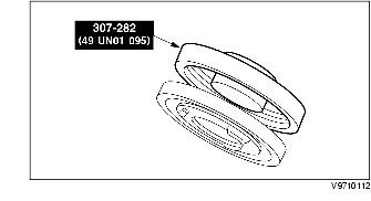
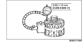
19. Measure the direct clutch clearance as follows:
-
• Install the SST.
-
• Zero the dial on the direct clutch pressure plate.
-
• Pull the direct clutch pressure plate upward, and record the reading.
20. Make a second measurement on the opposite side. Average the two measurements to get the clearance. If the clearance is not within the specification, select and install, using the SST, the correct thickness direct clutch pressure plate retainer snap ring to obtain the standard clearance.
-
• Retaining ring sizes:
-
• 1.28-1.38 mm {0.050-0.054 in}
-
• 1.39-1.49 mm {0.054-0.058 in}
-
• 1.52-1.62 mm {0.059-0.063 in}
-
• 1.65-1.75 mm {0.064-0.069 in}