AUTOMATIC TRANSAXLE AND TRANSFER DISASSEMBLY
BUE051700000A08
Precaution
General notes
1. The oil pan could contain small chips, shavings, and other particles which may be helpful in inspecting the condition of the transaxle and diagnosing certain problems. To ensure that all foreign particles stay in the oil pan, make sure that the transaxle is never tipped completely over while the oil pan is still installed.
-
a. Disassemble the transaxle in a clean area (dust proof work space) to prevent entry of dust into the mechanisms.
-
b. Inspect the individual transaxle components in accordance with the QUICK DIAGNOSIS CHART during disassembly.
-
c. Use only plastic hammers when applying force to separate the light alloy case joints.
-
d. Never use rags during disassembly; they may leave particles that can clog fluid passage.
-
e. Several parts resemble one another, arrange them so that they do not get mixed up.
-
f. Disassemble the control valve component and thoroughly clean it when the clutch or brake band has burned or when the ATF has degenerated.
-
Warning
-
• Although the stand has a self-locking brake system, there is a possibility that the brake may not hold when the transaxle is held in a lopsided position on the stand. This would cause the transaxle to turn suddenly, causing serious injury. Never keep the transaxle tilted to one side. Always hold the rotating handle firmly when turning the transaxle.
Disassembly
Components

.
|
1
|
Torque converter
|
|
2
|
Oil pump shaft
|
|
3
|
Oil dipstick and oil filler tube
|
|
4
|
Transfer
|
|
5
|
Input/turbine speed sensor
|
|
6
|
TR switch
|
|
7
|
Oil pipe
|
|
8
|
Oil pan
|
|
9
|
Oil strainer
|
|
10
|
Control valve body cover
|
|
11
|
Coupler component
|
|
12
|
Control valve body
|
|
13
|
Oil pump
|
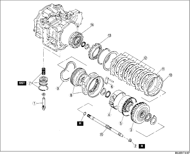
.
|
1
|
Piston stem
|
|
2
|
Snap ring
|
|
3
|
Clutch component
|
|
4
|
2-4 brake band
|
|
5
|
Small sun gear and one-way clutch 1
|
|
6
|
Anchor strut and shaft
|
|
7
|
Band servo
|
|
8
|
One-way clutch 2 and carrier hub component
|
|
9
|
Friction plate
|
|
10
|
Snap ring
|
|
11
|
Retaining plate
|
|
12
|
Low and reverse brake
|
|
13
|
Internal gear
|
|
14
|
3-4 clutch
|
|
15
|
Turbine shaft
|

.
|
1
|
Transaxle case
|
|
2
|
Output shell
|
|
3
|
Low and reverse brake piston
|
|
4
|
Detent spring
|
|
5
|
Manual shaft and manual plate
|
|
6
|
Actuator support
|
|
7
|
Parking assist lever
|
|
8
|
Parking pawl
|
|
9
|
Baffle plate
|
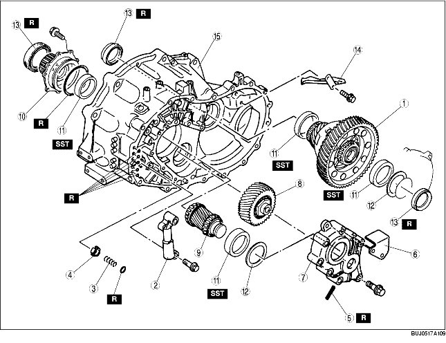
.
|
1
|
Front differential
|
|
2
|
2-3 accumulator
|
|
3
|
Orifice check valve spring
|
|
4
|
Orifice check valve
|
|
5
|
Roll pin
|
|
6
|
Baffle plate
|
|
7
|
Bearing housing
|
|
8
|
Idler gear
|
|
9
|
Output gear
|
|
10
|
Bearing cover component
|
|
11
|
Bearing races
|
|
12
|
Adjustment shim (bearing preload)
|
|
13
|
Oil seal
|
|
14
|
Baffle plate
|
|
15
|
Converter housing
|
Disassembly procedure
1. Remove the torque converter, and immediately turn it so that the hole faces upward. This will help to keep any remaining fluid from spilling.
2. Pull out the oil pump shaft by hand.
3. Remove the oil dipstick and oil filler tube.
4. Remove the O-ring from the oil filler tube.
5. Remove the breather hose.
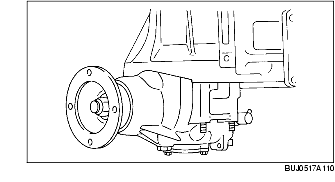
6. Remove the transfer.
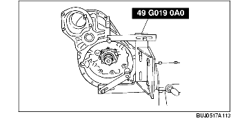
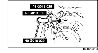
7. Assemble the SST.
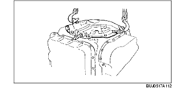
8. Attach suitable hangers to the oil pump as shown.
9. Lift the transaxle and mount it on the SST.
-
Note
-
• When the manual shaft lever is installed to the manual shaft, use an adjustable wrench to hold the manual shaft lever, then use a wrench other than an impact wrench to remove the manual shaft nut and manual shaft lever.
-
Caution
-
• Do not use an impact wrench or remove the manual shaft nut without holding the manual shaft lever, as the transaxle may become damaged.
10. Remove the manual shaft nut.
11. Remove the input/turbine speed sensor, TR switch, and bracket.
12. Remove the O-ring from the input/turbine speed sensor.
13. Disconnect the coupler.
14. Remove the connector bolt.
15. Remove the oil pipe, packing, spring, and steel ball.
-
Warning
-
• Using compressed air can cause dirt and other particles to fly out, causing injury to the eyes. Wear protective eye wear whenever using compressed air.
-
Caution
-
• Clean the transaxle exterior thoroughly with a steam cleaner or cleaning solvents before removal.
-
• If any old sealant gets into the transaxle during installation of the oil pan, trouble may occur in the transaxle. Remove any old sealant from the transaxle case and oil pan, and clean with cleaning fluids.
16. Remove the oil pan and inspect any material found in the pan or on the magnet to determine the condition of the transaxle.
-
• If large amounts of material are found, replace the torque converter and carefully check the transaxle for the cause.
-
- Clutch facing material: Drive plate and brake band wear
-
- Steel (magnetic): Bearing, gear, and driven plate wear
-
- Aluminum (nonmagnetic): Aluminum part wear
17. Remove the oil strainer and O-ring.
-
Caution
-
• If any old sealant gets into the transaxle during installation of the control valve body cover, trouble may occur in the transaxle. Remove any old sealant from the transaxle case and control valve body cover, and clean with cleaning fluids.
18. Remove the control valve body cover.
19. Disconnect the solenoid connectors and TFT sensor connector.
20. Remove the coupler component.
21. Remove the O-ring from the coupler component.
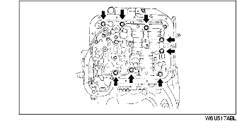
22. Loosen the indicated bolts evenly and gradually.
23. Remove the control valve body as an assembly.
24. Remove the oil pump and gasket.
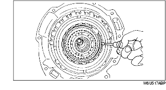
25. Remove the clutch component.
-
(1) Remove the turbine shaft snap ring.
-
(2) Pull the reverse and forward drum and remove the clutch component.
26. Remove the small sun gear and one-way clutch 1.
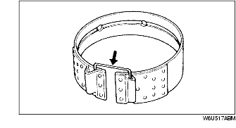
27. Remove the 2-4 brake band, and hold it together using a piece of wire as shown in the figure.
28. Pull out the anchor shaft while holding the strut, then remove the strut.
29. Remove the piston stem from the band servo.
30. Remove the band servo.
-
(1) Remove the snap ring using the SST.
-
(2) Remove the band servo and spring.
31. Remove the one-way clutch 2 and carrier hub component.
-
(1) Remove the snap ring.
-
(2) Remove the one-way clutch 2 together with the carrier hub component.
32. Remove the friction plate.
33. Remove the internal gear.
-
(1) Remove the snap ring from the output shell.
-
(2) Remove the internal gear from the output shell.
34. Remove the 3-4 clutch and turbine shaft.
-
(1) Remove the O-ring from the turbine shaft at the converter housing side.
-
(2) Remove the turbine shaft and 3-4 clutch together as an assembly.
-
(3) Separate the turbine shaft and 3-4 clutch.
-
Caution
-
• If any old sealant gets into the transaxle during installation of the transaxle case, trouble may occur in the transaxle. Remove any old sealant from the transaxle case and converter housing, and clean with cleaning fluids.
35. Remove the bolts and remove the transaxle case by tapping lightly with a plastic hammer.
36. Remove the output shell from the output gear.
37. Remove the manual shaft and manual plate.
-
(1) Remove the plug, packing, spring and detent ball.
-
(2) Loosen the nut and pull out the manual shaft.
-
(3) Remove the nut, washer, spacer, and manual plate.
38. Remove the differential.
39. Remove the 2-3 accumulator.
40. Remove the orifice check valve spring and orifice check valve.
41. Remove the baffle plate.
42. Remove the bearing housing.
-
(1) Remove the roll pin using a pin punch.

-
(2) Remove the baffle plate.
-
(3) Remove the bearing housing by tapping lightly with a plastic hammer.
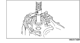
43. Remove the idler gear and output gear by tapping it out from the torque converter side.
44. Remove the bearing cover component.
-
(1) Remove the bearing cover bolts.
-
(2) Remove the converter housing from the SST (transaxle hanger).
-
(3) Press the bearing cover out of the converter housing using a suitable pipe.
-
Outer diameter of pipe
-
80 mm {3.1 in}
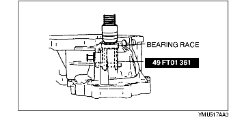
45. Press out the bearing race using the SST.