IDLER GEAR ASSEMBLY
BUE051719203A02
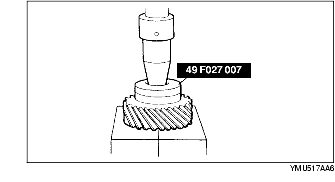
1. Press the new bearing races in using the SST.
2. Install a new bearing onto the idle gear shaft, and install the idler gear, spacer, and bearing component.
3. Secure the SST and the idler gear shaft component in a vise.
4. Install the locknut.
-
Tightening torque
-
148-196 N·m {15-20 kgf·m, 109-144 ft·lbf}
-
Caution
-
• Use protective plates in the vise to prevent damage to the idler gear.
-
Note
-
• Read the preload when the idler shaft starts to turn.
5. Secure the idler gear in a vise.
-
Note
-
• Measure several times and calculate the average value.
6. Measure the bearing preload using the SSTs.
-
• If the specified preload cannot be obtained within the specified tightening torque, adjust it by selecting the proper spacer from below.
-
Note
-
• Preload is reduced by increasing the thickness of the spacer or increased by reducing the thickness.
Thickness of spacer
mm {in}
|
4.540 {0.179}
|
4.575 {0.180}
|
4.610 {0.181}
|
4.645 {0.183}
|
|
4.680 {0.184}
|
4.715 {0.186}
|
4.750 {0.187}
|
4.785 {0.188}
|
|
4.820 {0.190}
|
4.855 {0.191}
|
4.890 {0.193}
|
4.925 {0.194}
|
|
4.960 {0.195}
|
4.995 {0.197}
|
5.030 {0.198}
|
5.065 {0.199}
|
|
5.100 {0.201}
|
5.135 {0.202}
|
5.170 {0.204}
|
5.205 {0.205}
|
|
5.240 {0.206}
|
5.275 {0.208}
|
5.310 {0.209}
|
-
|
-
Pull scale reading
-
0.3-8.8 N {0.03-0.9 kgf, 0.07-1.98 lbf}
-
Preload
-
0.03-0.8 N·m {0.3-9.0 kgf·cm, 0.27-7.8 in·lbf}
7. Apply ATF to a new O-ring and install it to the idler gear shaft.
-
O-ring inner diameter
-
33.0 mm {1.30 in}