.
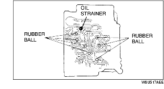
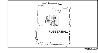
1. Install the oil strainer and rubber balls into the main control valve body.
2. Install the oil strainer and rubber ball into the rear control valve body.
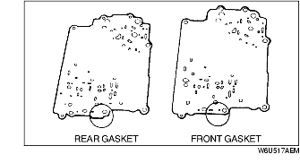
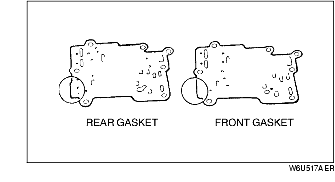
3. Set the new main/rear front gasket, rear separator plate, and new main/rear rear gasket on the rear control valve body. Refer to the figure to distinguish the two gaskets.
4. Set the rear control valve body onto the main control valve body.
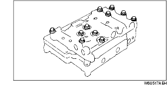
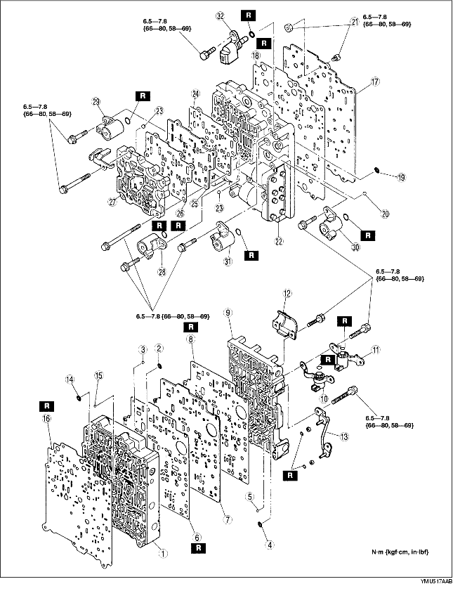
5. Install and hand-tighten the bolts shown in the figure. Each type of bolt has a different letter on its head. Match the bolt letter with the letter stamped next to its installation hole on the valve body.
6. Install the oil strainers and rubber balls into the main control valve body.
7. Install the oil strainer and rubber balls into the premain control valve body.
8. Install the jet orifice and nuts to the main separator plate.
9. Set a new premain/main rear gasket, main separator plate, and new premain/main front gasket on the premain control valve body. Refer to the figure to distinguish the two gaskets.
10. Set the premain control valve body onto the main control valve body.
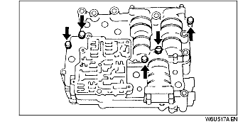
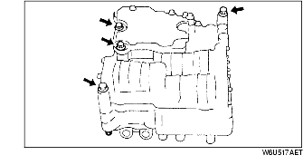
11. Install and hand-tighten the bolts indicated by the arrows. Each type of bolt has a different letter on its head. Match the bolt letter with the letter stamped next to its installation hole on the valve body.
12. Install the rubber ball into the premain control valve body.
13. Install the rubber ball into the front control valve body.
14. Set a new front/premain rear gasket, premain separator plate, and new front/premain front gasket on the front control valve body. Refer to the figure to distinguish the two gaskets.
15. Set the front control valve body onto the premain control valve body.
16. Install and hand-tighten the bolts indicated by the arrows. Each type of bolt has a different letter on its head. Match the bolt letter with the letter stamped next to its installation hole on the valve body.
17. Install four control valve body bolts as shown for alignment.
18. Tighten the mounting bolts.
19. Apply ATF to new O-rings and install them onto the solenoid valve.
20. Install the solenoid valve.
21. Apply ATF to new O-ring and install them onto the oil pipe component.
22. Install the oil pipe component.
23. Install the baffle plate.
24. Install the TFT sensor.