|
1
|
VERIFY FREEZE FRAME DATA AND DIAGNOSTIC MONITORING TEST RESULTS HAS BEEN RECORDED
• Has FREEZE FRAME DATA been recorded?
|
Yes
|
Go to the next step.
|
|
No
|
Record the FREEZE FRAME on the repair order, then go to the next step.
|
|
2
|
VERIFY RELATED SERVICE INFORMATION AVAILABILITY
• Verify related Service Information availability.
• Is any related Service Information available?
|
Yes
|
Perform repair or diagnosis according to the available Service Information.
If the vehicle is not repaired, go to the next step.
|
|
No
|
Go to the next step.
|
|
3
|
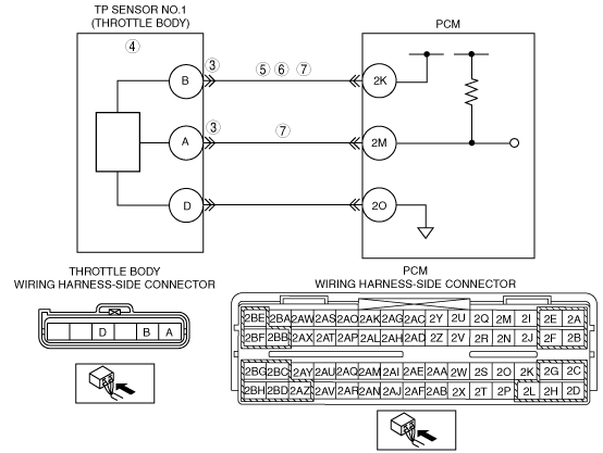
CLASSIFY TP SENSOR OR WIRING HARNESS MALFUNCTION
• Connect the M-MDS.
• Access TP1 PID.
• Disconnect throttle body connector.
• Connect a jumper wire between throttle body terminals A and B (wiring harness-side).
• Is the voltage above 4.9 V?
|
Yes
|
Go to the next step.
|
|
No
|
Go to Step 5.
|
|
4
|
INSPECT TP SENSOR
• Is TP sensor okay?
|
Yes
|
Inspect throttle body connector terminal B for poor connection. Repair or replace if necessary, then go to Step 8.
|
|
No
|
Replace the throttle body, then go to Step 8.
|
|
5
|
INSPECT POWER SUPPLY CIRCUIT VOLTAGE AT THROTTLE BODY CONNECTOR
-
Note
-
• If DTC P0107 and P2228 are also retrieved with P0122, go to CONSTANT VOLTAGE troubleshooting procedure.
• Turn the ignition switch to the ON position (Engine off).
• Measure the voltage at throttle body terminal B (wiring harness-side).
• Is the voltage within 4.5—5.5 V?
|
Yes
|
Go to the next step.
|
|
No
|
Repair or replace for an open circuit between throttle body connector terminal B (wiring harness-side) and PCM connector terminal 2K (wiring harness-side).
Then, then go to Step 8.
|
|
6
|
VERIFY TP1 SIGNAL CIRCUIT FOR OPEN CIRCUIT
• Turn the ignition switch off.
• Inspect for continuity between throttle body terminal B (wiring harness-side) and PCM terminal 2K (wiring harness-side).
• Is there continuity?
|
Yes
|
Go to the next step.
|
|
No
|
Repair or replace the wiring harness, then go to Step 8.
|
|
7
|
VERIFY TP1 SIGNAL CIRCUIT FOR SHORT TO GROUND
• Inspect for continuity between the following terminals (wiring harness-side) and body ground.
-
― Throttle body terminal A
― Throttle body terminal B
• Is there continuity?
|
Yes
|
Repair or replace the wiring harness, then go to the next step.
|
|
No
|
Go to the next step.
|
|
8
|
VERIFY TROUBLESHOOTING OF DTC P0122 COMPLETED
• Make sure to reconnect all disconnected connectors.
• Turn the ignition switch to the ON position (Engine off).
• Clear the DTC from the PCM memory using the M-MDS.
• Start the engine and warm it up completely.
• Is the same DTC present?
|
Yes
|
Replace the PCM, then go to the next step.
|
|
No
|
Go to the next step.
|
|
9
|
VERIFY AFTER REPAIR PROCEDURE
• Perform the “AFTER REPAIR PROCEDURE”.
• Is any DTC present?
|
Yes
|
Go to the applicable DTC inspection.
|
|
No
|
Troubleshooting completed.
|