 |
beleue00000039
VALVE CLEARANCE ADJUSTMENT [L3]
id0110a4803300
1. Disconnect the negative battery cable.
2. Remove the splash shield (RH).
3. Remove the ignition coils. (See IGNITION COIL REMOVAL/INSTALLATION [L3])
4. Disconnect the oil control valve (OCV) connector.
5. Remove the ventilation hose.
6. Remove the cylinder head cover.
7. Remove the drive belt. (See DRIVE BELT REMOVAL/INSTALLATION [L3].)
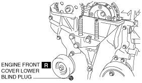
8. Remove the engine front cover lower blind plug.
beleue00000039
|
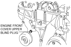
9. Remove the engine front cover upper blind plug.
beleue00000040
|
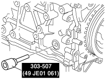
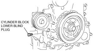
10. Remove the cylinder block lower blind plug, and install the SST.
ampjjw00002884
|
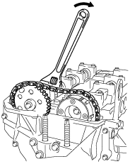
11. Rotate the crankshaft in the direction of the engine rotation so that the No.1 piston is at TDC of the compression stroke. (Until the counterweight contacts SST and stops.)
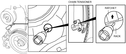
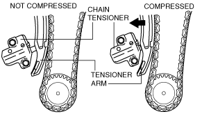
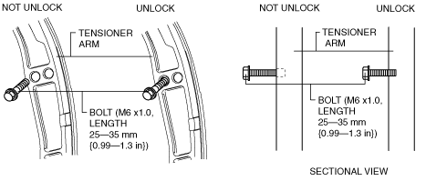
12. Loosen the timing chain using the following procedure.
beleue00000041
|
aatjjw00004131
|
atraaw00003489
|
aatjjw00004013
|
beleue00000042
|
am6xuw00002058
|
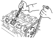
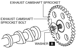
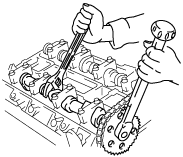
13. Fix the exhaust camshaft using a wrench on the cast hexagon, and loosen the camshaft sprocket bolt.
acxuuw00000161
|
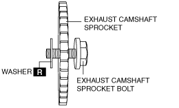
14. Remove the exhaust camshaft sprocket bolt, exhaust camshaft sprocket, and washer as a single unit.
beleue00000044
|
15. Remove the oil control valve (OCV). (See OIL CONTROL VALVE (OCV) REMOVAL/INSTALLATION [L3].)
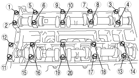
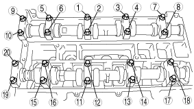
16. Loosen the camshaft cap bolts in several passes in the order shown.
atraaw00002272
|
17. Remove the camshafts for the intake and exhaust sides.
18. Remove the tappet.
19. Select proper adjustment shim.
20. Verify that the No.1 cylinder is at TDC of the compression stroke. (The position counter weight contacts the SST.)
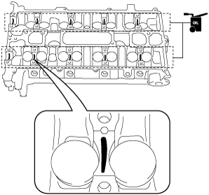
21. Apply the gear oil (SAE No. 90 or equivalent) to each journal of the cylinder head as shown in the figure.
atraaw00003476
|
22. Install the camshaft with No.1 cylinder aligned with the TDC position.
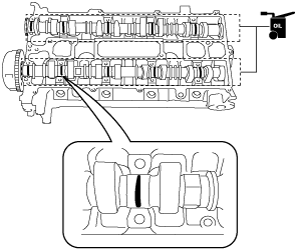
23. Apply the gear oil (SAE No. 90 or equivalent) to each journal of the camshaft as shown in the figure.
atraaw00003477
|
24. Temporarily tighten the camshaft cap bolts evenly in 2—3 steps.
25. Tighten the camshaft cap bolts in the order shown in the following two steps.
atraaw00002273
|
26. Install the OCV. (See OIL CONTROL VALVE (OCV) REMOVAL/INSTALLATION [L3].)
27. Install the exhaust camshaft sprocket bolt, exhaust camshaft sprocket, and a new washer as a single unit.
atraaw00003491
|
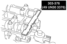
28. Install the SST to the camshaft as shown.
aaxjjw00002211
|
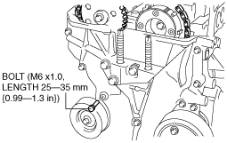
29. Remove the installation bolt for the engine front cover upper blind plug (M6 X 1.0 length 25—35mm {0.99—1.3 in}), and apply tension to the timing chain.
30. Rotate the crankshaft clockwise and verify that the No.1 cylinder is at TDC of the compression stroke. (The position counter weight contacts the SST.)
31. Fix the exhaust camshaft using a wrench on the cast hexagon, and tighten the sprocket bolt.
am8rrw00002546
|
32. Remove the SST from the camshaft.
33. Remove the SST from the block lower blind plug.
34. Rotate the crankshaft clockwise two turns until the TDC position.
35. Apply the silicone sealant and install the engine front cover upper blind plug.
beleue00000040
|
36. Install the cylinder block lower blind plug.
am3zzw00004791
|
37. Install a new engine front cover lower blind plug.
beleue00000039
|
38. Install the drive belt. (See DRIVE BELT REMOVAL/INSTALLATION [L3].)
39. Install the cylinder head cover.
40. Install the ventilation hose.
41. Connect the oil control valve (OCV) connector.
42. Install the ignition coils. (See IGNITION COIL REMOVAL/INSTALLATION [L3])
43. Install the splash shield (RH).
44. Connect the negative battery cable.