 |
atraaw00001595
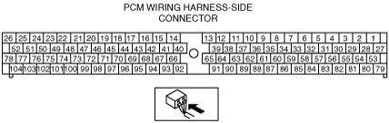
PCM INSPECTION[AJ (3.0L Duratec)]
id0140a1802500
1. Disconnect the negative battery cable.
2. Remove the PCM.
3. Connect the powertrain control module (PCM) electrical connector.
4. Connect the negative battery cable.
5. Connect the negative (–) lead of the circuit tester to the body ground.
6. Measure the voltage at each PCM terminal using the (digital) circuit tester.
Terminal Voltage Table (Reference)
atraaw00001595
|
|
Terminal |
Signal name |
Connected to |
Measurement condition |
Voltage (V) |
Inspection item |
|
|---|---|---|---|---|---|---|
|
1
|
Ignition coil control
|
Ignition coil
|
• Ignition coil
• Related wiring harness
|
|||
|
2
|
—
|
—
|
—
|
—
|
—
|
|
|
3
|
Ground
|
Ground
|
Under any condition
|
1.0 or less
|
• Related wiring harness
|
|
|
4
|
—
|
—
|
—
|
—
|
—
|
|
|
5
|
—
|
—
|
—
|
—
|
—
|
|
|
6
|
Shift solenoid A control
|
Shift solenoid A
|
Solenoid valve operating
|
B+
|
• Shift solenoid A
• Related wiring harness
|
|
|
Solenoid valve not operating
|
1.0 or less
|
|||||
|
7
|
—
|
—
|
—
|
—
|
—
|
|
|
8
|
—
|
—
|
—
|
—
|
—
|
|
|
9
|
—
|
—
|
—
|
—
|
—
|
|
|
10
|
—
|
—
|
—
|
—
|
—
|
|
|
11
|
Shift solenoid B control
|
Shift solenoid B
|
Solenoid valve operating
|
B+
|
• Shift solenoid B
• Related wiring harness
|
|
|
Solenoid valve not operating
|
1.0 or less
|
|||||
|
12
|
—
|
—
|
—
|
—
|
—
|
|
|
13
|
—
|
—
|
—
|
—
|
—
|
|
|
14
|
—
|
—
|
—
|
—
|
—
|
|
|
15
|
BUS-
|
M-MDS
|
As this terminal is for communication, terminal voltage inspection is not suitable for determination.Inspect with DTC inspection.
|
• Related wiring harness
|
||
|
16
|
BUS+
|
M-MDS
|
As this terminal is for communication, terminal voltage inspection is not suitable for determination.Inspect with DTC inspection.
|
• Related wiring harness
|
||
|
17
|
Key ID
|
Coil antenna
|
As this terminal is for communication, terminal voltage inspection is not suitable for determination.
Inspect with DTC inspection.
|
• Coil antenna
• Related wiring harness
|
||
|
18
|
Key ID
|
Coil antenna
|
As this terminal is for communication, terminal voltage inspection is not suitable for determination.
Inspect with DTC inspection.
|
• Coil antenna
• Related wiring harness
|
||
|
19
|
—
|
—
|
—
|
—
|
—
|
|
|
20
|
3-2 timing/coast clutch solenoid valve control
|
3-2 timing/coast clutch solenoid valve
|
Solenoid valve operating
|
B+
|
• 3-2 timing/coast clutch solenoid valve
• Related wiring harness
|
|
|
Solenoid valve not operating
|
1.0 or less
|
|||||
|
21
|
Engine rotation
(+)
|
CKP sensor
|
• CKP sensor
• Related wiring harness
|
|||
|
22
|
Engine rotation
(–)
|
CKP sensor
|
• CKP sensor
• Related wiring harness
|
|||
|
23
|
—
|
—
|
—
|
—
|
—
|
|
|
24
|
Ground
|
Ground
|
Under any condition
|
1.0 or less
|
• Related wiring harness
|
|
|
25
|
Ground
|
Ground
|
Under any condition
|
1.0 or less
|
• Related wiring harness
|
|
|
26
|
Ignition coil control
|
Ignition coil
|
• Ignition coil
• Related wiring harness
|
|||
|
27
|
Ignition coil control
|
Ignition coil
|
• Ignition coil
• Related wiring harness
|
|||
|
28
|
Low speed control fan relay control
|
Cooling fan relay No.2
|
While idling
|
Cooling fan on
|
1.0 or less
|
• Cooling fan relay No.2
• Related wiring harness
|
|
Cooling fan off
|
B+
|
|||||
|
29
|
O/D OFF
|
O/D OFF switch
|
Ignition switch at ON
|
While O/D OFF switch is pressed
|
B+
|
• O/D OFF switch inspection
• Related wiring harness
|
|
Except when O/D OFF switch is pressed
|
1.0 or less
|
|||||
|
30
|
—
|
—
|
—
|
—
|
—
|
|
|
31
|
PSP
|
PSP switch
|
While idling
|
Steering wheel neutral
|
B+
|
• PSP switch
• Related wiring harness
|
|
While steering wheel is turned
|
1.0 or less
|
|||||
|
32
|
—
|
—
|
—
|
—
|
—
|
|
|
33
|
—
|
—
|
—
|
—
|
—
|
|
|
34
|
—
|
—
|
—
|
—
|
—
|
|
|
35
|
Rear HO2S (RH)
|
Rear HO2S (RH)
|
Idle after warm-up
|
Alternates between 0 and 1.0
|
• Rear HO2S (RH)
• Related wiring harness
|
|
|
36
|
Input device ground
|
MAF sensor
|
Under any condition
|
1.0 or less
|
• MAF sensor
• Related wiring harness
|
|
|
37
|
ATF temperature
|
TFT sensor
|
Ignition switch at ON
|
At ATF temperature 20 °C {68 °F}
|
3―4
|
• TFT sensor
• Related wiring harness
|
|
At ATF temperature 130 °C {266 °F}
|
0.2―0.7
|
|||||
|
38
|
ECT
|
ECT sensor
|
Ignition switch at ON
|
ECT is 20 °C {68 °F}
|
Approx. 3.1
|
• ECT sensor
• Related wiring harness
|
|
ECT is 60 °C {140 °F}
|
Approx. 1.4
|
|||||
|
ECT is 80 °C {176 °F}
|
Approx. 0.9
|
|||||
|
39
|
Intake air temperature
|
IAT sensor
|
Ignition switch at ON
|
At IAT 20 °C {68 °F}
|
Approx. 2.5
|
• IAT sensor
• Related wiring harness
|
|
At IAT 30 °C {86 °F}
|
Approx. 1.8
|
|||||
|
40
|
Fuel pump operation detection
|
Fuel pump relay
|
Ignition switch at ON
|
1.0 or less
|
• Fuel pump relay
• Related wiring harness
|
|
|
Cranking
|
B+
|
|||||
|
While idling
|
||||||
|
41
|
A/C signal
|
Refrigerant pressure switch (low, high pressure), A/C switch
|
While idling
|
A/C on
|
1.0 or less
|
• A/C switch
• Refrigerant pressure switch (low, high pressure)
• Related wiring harness
|
|
A/C off
|
B+
|
|||||
|
42
|
—
|
—
|
—
|
—
|
—
|
|
|
43
|
—
|
—
|
—
|
—
|
—
|
|
|
44
|
Starter cut control
|
Starter relay
|
P or N position
|
B+
|
• Starter relay
• Related wiring harness
|
|
|
Except above
|
1.0 or less
|
|||||
|
45
|
—
|
—
|
—
|
—
|
—
|
|
|
46
|
High speed control fan relay control
|
Cooling fan relay No.1, Cooling fan relay No.3
|
While idling
|
Cooling fan on
|
1.0 or less
|
• Cooling fan relay No.1, Cooling fan relay No.3
• Related wiring harness
|
|
Cooling fan off
|
B+
|
|||||
|
47
|
EGR control valve control
|
EGR control valve
|
While idling
|
B+
|
• EGR control valve
• Related wiring harness
|
|
|
48
|
—
|
—
|
—
|
—
|
—
|
|
|
49
|
—
|
—
|
—
|
—
|
—
|
|
|
50
|
—
|
—
|
—
|
—
|
—
|
|
|
51
|
Ground
|
Ground
|
Under any condition
|
1.0 or less
|
• Related wiring harness
|
|
|
52
|
Ignition coil control
|
Ignition coil
|
• Ignition coil
• Related wiring harness
|
|||
|
53
|
Ignition coil control
|
Ignition coil
|
• Ignition coil
• Related wiring harness
|
|||
|
54
|
Torque converter clutch control
|
Torque converter clutch solenoid valve
|
Solenoid valve operating
|
B+
|
• Torque converter clutch solenoid valve
• Related wiring harness
|
|
|
Solenoid valve not operating
|
1.0 or less
|
|||||
|
55
|
Backup power supply
|
Battery
|
Under any condition
|
B+
|
• Battery
• Main fuse
• Related wiring harness
|
|
|
56
|
Evaporative purge control
|
Purge solenoid valve
|
• Purge solenoid valve
• Related wiring harness
|
|||
|
57
|
—
|
—
|
—
|
—
|
—
|
|
|
58
|
—
|
—
|
—
|
—
|
—
|
|
|
59
|
Turbine speed
|
TSS sensor
|
• TSS sensor
• Related wiring harness
|
|||
|
60
|
Front HO2S (RH)
|
Front HO2S (RH)
|
• Front HO2S (RH)
• Related wiring harness
|
|||
|
61
|
Rear HO2S (LH)
|
Rear HO2S (LH)
|
Idle after warm-up
|
Alternates between 0 and 1.0
|
• Rear HO2S (LH)
• Related wiring harness
|
|
|
62
|
—
|
—
|
—
|
—
|
—
|
|
|
63
|
—
|
—
|
—
|
—
|
—
|
|
|
64
|
TR
|
TR switch
|
Ignition switch at ON
|
P position
|
Approx. 4.4
|
• TR switch
• Related wiring harness
|
|
R position
|
Approx. 3.6
|
|||||
|
N position
|
Approx. 2.9
|
|||||
|
D range
|
Approx. 2.1
|
|||||
|
2 Range
|
Approx. 1.4
|
|||||
|
1 Range
|
Approx. 0.7
|
|||||
|
65
|
EGR flow
|
D.P.F. EGR sensor
|
While idling after warm-up
|
Approx. 1
|
• D.P.F. EGR sensor
• Related wiring harness
|
|
|
66
|
—
|
—
|
—
|
—
|
—
|
|
|
67
|
—
|
—
|
—
|
—
|
—
|
|
|
68
|
—
|
—
|
—
|
—
|
—
|
|
|
69
|
A/C control
|
A/C relay
|
A/C on
|
1.0 or less
|
• A/C relay
• Related wiring harness
|
|
|
70
|
—
|
—
|
—
|
—
|
—
|
|
|
71
|
Power supply
|
Main relay
|
Ignition switch at ON
|
B+
|
• Main relay
• Related wiring harness
|
|
|
Ignition switch is off.
|
1.0 or less
|
|||||
|
72
|
—
|
—
|
—
|
—
|
—
|
|
|
73
|
Fuel injector No.5 control
|
Fuel injector No.5
|
• Fuel injector
• Related wiring harness
|
|||
|
74
|
Fuel injector No.3 control
|
Fuel injector No.3
|
• Fuel injector
• Related wiring harness
|
|||
|
75
|
Fuel injector No.1 control
|
Fuel injector No.1
|
• Fuel injector
• Related wiring harness
|
|||
|
76
|
Ground
|
Ground
|
Under any condition
|
1.0 or less
|
• Related wiring harness
|
|
|
77
|
—
|
—
|
—
|
—
|
—
|
|
|
78
|
Ignition coil control
|
Ignition coil
|
• Ignition coil
• Related wiring harness
|
|||
|
79
|
—
|
—
|
—
|
—
|
—
|
|
|
80
|
Fuel pump control
|
Fuel pump relay
|
Ignition switch at ON
|
B+
|
• Fuel pump relay
• Related wiring harness
|
|
|
Cranking
|
1.0 or less
|
|||||
|
While idling
|
||||||
|
81
|
Electronic pressure control solenoid control
|
Electronic pressure control solenoid
|
• Electronic pressure control solenoid
• Related wiring harness
|
|||
|
82
|
—
|
—
|
—
|
—
|
—
|
|
|
83
|
IAC control
|
IAC solenoid valve
|
• IAC solenoid valve
• Related wiring harness
|
|||
|
84
|
Output shaft speed
|
Output shaft speed sensor
|
• Output shaft speed sensor
• Related wiring harness
|
|||
|
85
|
Cylinder identification
|
CMP sensor
|
• CMP sensor
• Related wiring harness
|
|||
|
86
|
Refrigerant pressure signal (medium pressure)
|
Refrigerant pressure switch (medium pressure)
|
While idling
|
Refrigerant pressure is more than the specification
|
1.0 or less
|
• Refrigerant pressure switch (medium pressure)
• Related wiring harness
|
|
Refrigerant pressure is less than the specification
|
B+
|
|||||
|
87
|
Front HO2S (LH)
|
Front HO2S (LH)
|
• Front HO2S (LH)
• Related wiring harness
|
|||
|
88
|
Intake air amount
|
MAF sensor
|
Ignition switch at ON
|
Approx. 0
|
• MAF sensor
• Related wiring harness
|
|
|
After warm-up, while idling (no electrical load, A/C off, P/S off)
|
Approx. 0.7
|
|||||
|
89
|
Throttle position
|
TP sensor
|
Ignition switch at ON
|
Accelerator closed
|
Approx. 0.9
|
• TP sensor
• Related wiring harness
|
|
Accelerator fully opened
|
Approx. 4.7
|
|||||
|
90
|
Constant voltage power supply
|
TP sensor, D.P.F. EGR sensor
|
Ignition switch
On
|
Approx. 5.0
|
• TP sensor
• D.P.F. EGR sensor
• Related wiring harness
|
|
|
91
|
Input device ground
|
TP sensor, MAF/IAT sensor, HO2S, D.P.F. EGR sensor, ECT sensor, TFT sensor, TR switch sensor
|
Under any condition
|
1.0 or less
|
• Related wiring harness
|
|
|
92
|
Brake
|
Brake switch
|
When brake pedal is depressed
|
B+
|
• Brake switch
• Related wiring harness
|
|
|
Except above
|
1.0 or less
|
|||||
|
93
|
Front HO2S heater (RH) control
|
Front HO2S heater (RH)
|
• Front HO2S (RH)
• Related wiring harness
|
|||
|
94
|
Front HO2S heater (LH) control
|
Front HO2S heater (LH)
|
• Front HO2S (RH)
• Related wiring harness
|
|||
|
95
|
Rear HO2S heater (RH) control
|
Rear HO2S heater (RH)
|
Heavy load (Heater control not operating)
|
B+
|
• Rear HO2S (RH) heater
• Related wiring harness
|
|
|
96
|
Rear HO2S heater (LH) control
|
Rear HO2S heater (LH)
|
Heavy load (Heater control not operating)
|
B+
|
• Rear HO2S (LH) heater
• Related wiring harness
|
|
|
97
|
Power supply
|
Main relay
|
Ignition switch at ON
|
B+
|
• Main relay
• Related wiring harness
|
|
|
Ignition switch is off.
|
1.0 or less
|
|||||
|
A/C off
|
B+
|
|||||
|
98
|
—
|
—
|
—
|
—
|
—
|
|
|
99
|
Fuel injector No.6 control
|
Fuel injector No.6
|
• Fuel injector
• Related wiring harness
|
|||
|
100
|
Fuel injector No.4 control
|
Fuel injector No.4
|
• Fuel injector
• Related wiring harness
|
|||
|
101
|
Fuel injector No.2 control
|
Fuel injector No.2
|
• Fuel injector
• Related wiring harness
|
|||
|
102
|
—
|
—
|
—
|
—
|
—
|
|
|
103
|
Ground
|
Ground
|
Under any condition
|
1.0 or less
|
• Related wiring harness
|
|
|
104
|
—
|
—
|
—
|
—
|
—
|
|
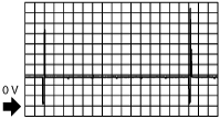
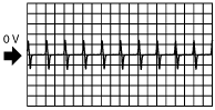
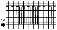
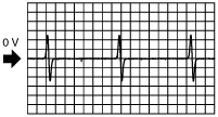
Inspection Using An Oscilloscope (Reference)
Ignition coil control signal
atraaw00000167
|
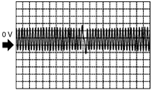
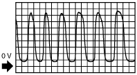
Engine speed signal
(+)
atraaw00000168
|
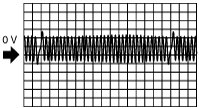
(–)
atraaw00000169
|
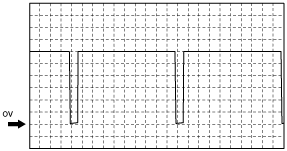
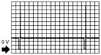
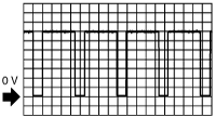
Purge solenoid valve control signal
atraaw00000170
|
Turbine speed signal
atraaw00000171
|
Oxygen concentration signal
atraaw00000172
|
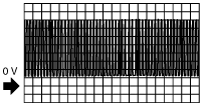
Fuel injector control signals
atraaw00000173
|
Electronic pressure control solenoid control
atraaw00000174
|
IAC control signal
atraaw00000175
|
Cylinder identification signal
atraaw00000176
|
HO2S heater control signal
atraaw00000177
|