 |
atraaw00002606
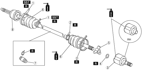
FRONT DRIVE SHAFT DISASSEMBLY/ASSEMBLY[L3]
id0313008004a1
1. Disassemble in the order indicated in the table.
2. Assemble in the reverse order of disassembly.
atraaw00002606
|
|
1
|
Boot band (wheel side)
|
|
2
|
Boot band (differential side)
|
|
3
|
Outer ring
(See Outer Ring Disassembly Note.)
(See Outer Ring Assembly Note.)
|
|
4
|
Snap ring
|
|
5
|
Tripod joint
|
|
6
|
Boot
(See Boot Disassembly Note.)
(See Boot Assembly Note.)
|
|
7
|
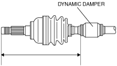
Dynamic damper
(See Dynamic Damper Assembly Note.)
|
|
8
|
Shaft, bell joint component
|
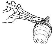
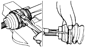
Boot Band (Wheel Side) Disassembly Note
1. Remove the boot band using end clamp pliers.
atraaw00002607
|
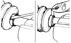
Boot Band (Differential Side) Disassembly Note
1. Press the lock clip upward using a flathead screwdriver.
2. Remove the boot band using pliers.
atraaw00002608
|
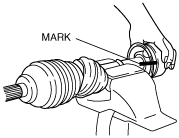
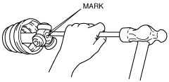
Outer Ring Disassembly Note
1. Place an alignment mark on the outer ring (tripod side) and the drive shaft.
atraaw00002609
|
2. Remove the outer ring.
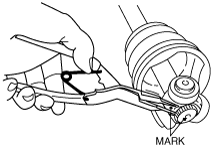
Snap Ring, Tripod Joint Disassembly Note
1. Place an alignment mark on the shaft and tripod joint.
atraaw00002610
|
2. Remove the snap ring from the shaft using snap ring pliers.
3. Remove the tripod joint.
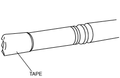
Boot Disassembly Note
1. Wrap the shaft splines with tape and remove the boot.
atraaw00002611
|
Dynamic Damper Assembly Note
1. Install the dynamic damper with the length shown in the figure within the specification.
atraaw00002612
|
Boot Assembly Note
1. Fill the inside of the new dust boot (wheel side) with grease.
2. Assemble the boot with the shaft spline wrapped with tape.
3. Remove the tape.
Tripod Joint, Snap Ring Assembly Note
1. While aligning the marks on the shaft and the tripod joint, insert the tripod joint.
atraaw00002613
|
2. Insert a new snap ring using snap ring pliers.
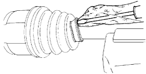
Outer Ring Assembly Note
1. Apply the outer ring and boot (differential side) with the repair kit grease.
2. Assemble the outer ring.
3. Set the drive shaft to the standard length.
4. Release any trapped air from the boots by carefully lifting up the small end of each boot with a clean rag-wrapped flathead screwdriver.
atraaw00002614
|
5. Verify that the drive shaft length is within the specification under atmospheric pressure inside the boot.
Boot Band (Differential Side) Assembly Note
1. Set a new boot band to the boot slot.
atraaw00002615
|
2. After pulling the tip of the boot band with pliers, crimp it.
3. Fold back the clip to secure the boot band.
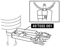
Boot Band (Wheel Side) Assembly Note
1. Adjust clearance A by turning the adjusting bolt of the SST.
atraaw00002616
|
2. Crimp the wheel side small boot band using the SST. Verify that clearance B is within the specification.
acxuuw00001252
|
3. Verify that the boot band does not protrude from the boot band installation area.
4. Fill the boot with the repair kit grease.
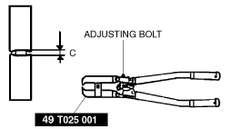
5. Adjust clearance C by turning the adjusting bolt of the SST.
atraaw00003134
|
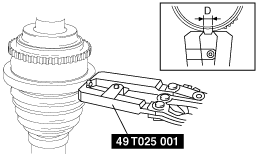
6. Crimp the wheel side big boot band using the SST.
7. Verify that clearance D is within the specification.
atraaw00003135
|
8. Verify that the boot band does not protrude from the boot band installation area.