 |
atraaw00002661
FRONT DRIVE SHAFT DISASSEMBLY/ASSEMBLY[AJ (3.0L Duratec)]
id0313008004a2
Disassembly
1. Remove the drive shaft. (See FRONT DRIVE SHAFT REMOVAL/INSTALLATION.)
2. Secure the drive shaft in a vice using protective jaw covers.
atraaw00002661
|
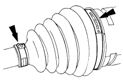
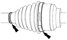
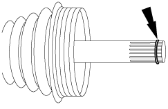
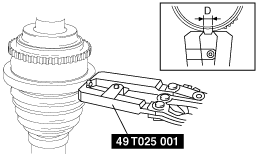
3. Remove the boot band.
atraaw00002662
|
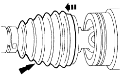
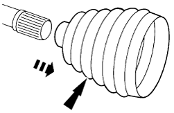
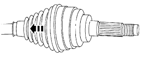
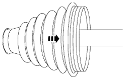
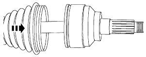
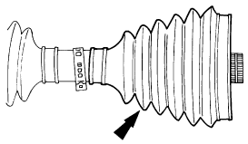
4. Slide and remove the boot.
atraaw00002663
|
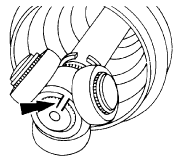
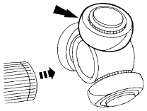
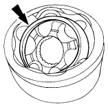
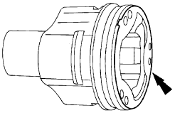
5. Disconnect the tripod joint from the outer ring.
atraaw00002664
|
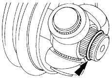
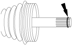
6. If reinstalling the tripod joint, mark the tripod joint and the drive shaft for correct installation.
atraaw00002665
|
7. Remove the snap ring.
atraaw00002666
|
8. Remove the tripod joint.
atraaw00002667
|
9. Remove the boot from the drive shaft.
atraaw00002668
|
10. Remove the two boot bands (wheel side).
atraaw00002669
|
11. Slide the boot back out of the way to expose the joint (wheel side).
atraaw00002670
|
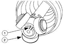
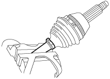
12. Remove and dispose the retainer clip.
atraaw00002671
|
13. Slide and remove the boot (wheel side) from the drive shaft.
atraaw00002672
|
Assembly
1. Lubricate the joint (wheel side) with the BALL JOINT ADDITIVE.
atraaw00002673
|
2. Install the boot.
atraaw00002674
|
3. Install a new retainer clip.
atraaw00002675
|
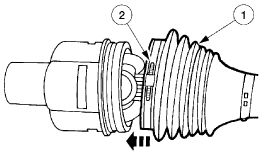
4. Remove any excess grease on the mating surfaces and slide the boot forward onto the joint.
atraaw00002676
|
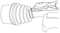
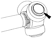
5. Remove any excess air trapped in the boot using a cloth covered screwdriver after installing the boot correctly.
acxuuw00001249
|
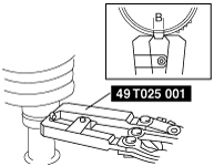
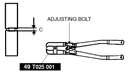
6. Assemble a new boot band.
atraaw00002616
|
acxuuw00001252
|
atraaw00003134
|
atraaw00003135
|
7. Fill the boot with the repair kit grease.
8. Position the boot (differential side).
atraaw00002678
|
9. Install the tripod joint to the drive shaft.
atraaw00002679
|
10. Install the snap ring.
atraaw00002680
|
11. Lubricate the three tripod joint needle bearings.
atraaw00002681
|
12. Lubricate inside the tripod joint with the BALL JOINT ADDITIVE.
atraaw00002682
|
13. Position the outer ring onto the tripod.
atraaw00002664
|
14. Position the boot (differential side).
atraaw00002683
|
15. Remove any excess air trapped in the boot using a cloth covered screwdriver after installing the boot correctly.
acxuuw00001249
|
16. Follow the same procedures to install the two new boot bands on the opposite side.
17. Install the drive shaft. (See FRONT DRIVE SHAFT REMOVAL/INSTALLATION.)