 |
atraaw00003195
REAR DIFFERENTIAL DISASSEMBLY/ASSEMBLY
id031400801000
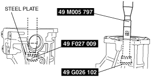
Disassembly
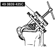
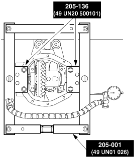
1. Install the SSTs to the engine stand.
atraaw00003195
|
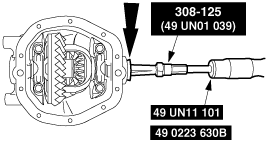
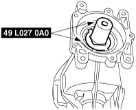
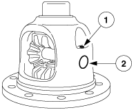
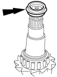
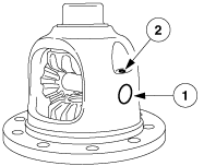
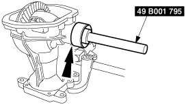
2. Remove the needle bearing and the oil seal using the SSTs.
atraaw00002722
|
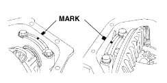
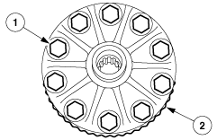
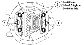
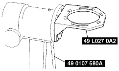
3. Place an alignment mark on the bearing cap and the carrier, and remove the bearing cap.
atraaw00002723
|
4. Remove the differential case using the SSTs.
atraaw00002724
|
5. Remove the SSTs.
atraaw00002725
|
6. Remove the locknut using the SSTs.
atraaw00002726
|
7. Remove the drive pinion, collapsible spacer and drive pinion bearings.
atraaw00002727
|
8. Remove the drive outer and inner drive pinion bearing cups using the SSTs.
atraaw00002728
|
9. Remove the oil baffle.
10. Remove the side bearing inner race from the gear case using the SST and a press.
atraaw00002729
|
atraaw00002730
|
11. Remove the ring gear.
atraaw00002731
|
12. Remove the differential pinion shaft.
atraaw00002732
|
13. Remove the two pinion gears, two side gears, and four thrust washers.
atraaw00002733
|
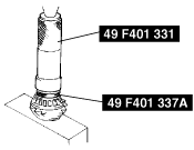
14. Remove the drive pinion bearing and the drive pinion position shim using the SSTs.
atraaw00002734
|
Assembly
1. Install a new oil baffle, and the inner and outer drive pinion bearing cups using the SSTs.
atraaw00002735
|
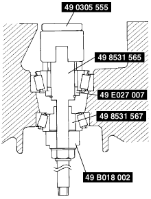
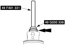
2. Assemble the spacer, bearing inner race (rear), and the O-ring of the SST to the SST (49 8531 565) as shown in the figure.
atraaw00002736
|
3. Insert the set assembled in Step 2 from the rear side of the differential carrier.
4. Assemble the bearing inner race (front), the SST (49 8531 567), the companion flange, the washer, and the locknut from the front side of the differential carrier.
5. Tighten the locknut to the extent that the SST (49 8531 565) can be turned by hand.
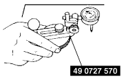
6. Place the SST (49 0305 555) on the SST (49 8531 565).
7. Place the SST on the surface plate and set the dial gauge to zero.
atraaw00003196
|
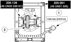
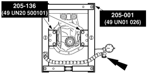
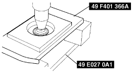
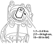
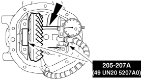
8. Set the SST as shown in the figure.
atraaw00002738
|
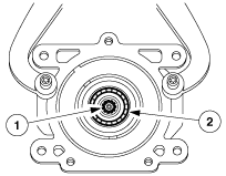
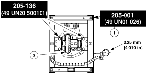
9. Place the measuring probe of the dial gauge at the point where the side bearing is installed in the carrier and measure at the lowest position. Measure at both side (left and right).
10. Add the two (left and right) values obtained by the measurements taken in Step 9 and divide the total by two. Add 0.3435 to the value, and subtract the value written on the drive pinion. This is the pinion height adjustment value. (If the value is plus, abate. If the value is minus, add.)
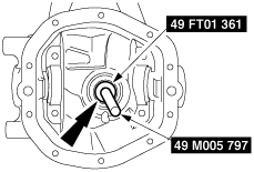
11. Install the drive pinion adjustment shim and the bearing using the SSTs.
atraaw00002739
|
12. Install a new collapsible spacer.
atraaw00002740
|
13. Install the drive pinion and a new drive pinion nut using the SST.
atraaw00002741
|
14. Inspect the drive pinion rotational torque and adjust if necessary.
atraaw00002742
|
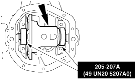
15. Install the differential case to the axle housing using the SST.
atraaw00002743
|
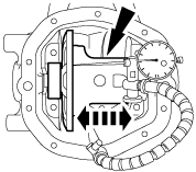
16. After assembling the differential case away from the drive pinion, measure and record the differential case total end play while pushing the differential case toward the drive pinion.
atraaw00002744
|
17. Remove the differential case and the SSTs.
atraaw00002743
|
18. Install the two pinion gears, two side gears and four thrust washers.
atraaw00002745
|
19. Install the differential pinion shaft.
atraaw00002746
|
20. Install the ring gear.
atraaw00002747
|
21. Install the differential case to the axle housing using the SSTs.
atraaw00002748
|
22. After assembling the differential case away from the drive pinion, measure and record the differential case total end play while pushing the differential case toward the drive pinion.
atraaw00002749
|
23. Remove the differential case and the SSTs.
atraaw00002748
|
24. Calculate for the differential case bearing shims as follows:
|
Differential case shim selection |
Value |
|
|---|---|---|
|
Step 1
|
Total differential case end play (without ring gear installed)
|
|
|
Step 2
|
Total differential case end play (with ring gear installed)
|
|
|
Step 3
|
Step 1 - Step 2
|
|
|
Step 4
|
Total shims necessary for the ring gear side of differential case (Step 2 + 0.076 mm {0.003 in})
|
|
|
Step 5
|
Total shims necessary for the opposite side of the ring gear of differential case (Step 3 + 0.25 mm) {0.01 in}
|
|
Example
|
Differential case shim selection |
Value |
|
|---|---|---|
|
Step 1
|
Total differential case end play (without ring gear installed)
|
1.066 mm {0.042 in}
|
|
Step 2
|
Total differential case end play (with ring gear installed)
|
0.660 mm {0.026 in}
|
|
Step 3
|
Step 1 - Step 2
|
0.406 mm {0.016 in}
|
|
Step 4
|
Total shims necessary for the ring gear side of differential case (Step 2 + 0.076 mm {0.003 in})
|
0.736 mm {0.029 in}
|
|
Step 5
|
Total shims necessary for the opposite side of the ring gear of differential case (Step 3 + 0.25 mm {0.01 in})
|
0.656 mm {0.026 in}
|
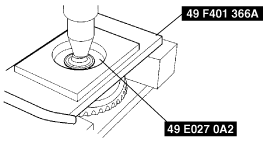
25. Measure the width of the SSTs used on the ends of the differential case and select differential case bearing shims if necessary.
26. Install the differential case bearings and correct shims using the SSTs.
atraaw00002750
|
27. Install the differential case using the SSTs.
atraaw00002751
|
28. Remove the SSTs.
atraaw00002752
|
29. Install the bearing caps.
atraaw00002753
|
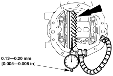
30. Measure and adjust the ring gear backlash if necessary.
atraaw00002754
|
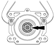
31. Position the axle component with the drive pinion stem facing upward.
32. Measure and record the total turning torque to rotate the drive pinion and adjust if necessary.
atraaw00002755
|
33. Install the needle bearings using the SSTs.
atraaw00002756
|
34. Install the oil seals using the SSTs.
atraaw00002757
|