 |
atraaw00002259
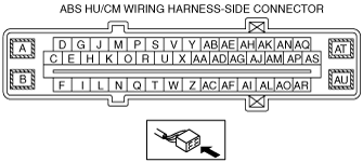
ABS HU/CM INSPECTION[L3]
id0413008010a1
1. Disconnect the ABS HU/CM connectors.
2. Connect the negative battery cable.
3. Attach the tester lead to the ABS HU/CM wiring harness-side connector, then inspect the voltage, continuity, or resistance according to the standard (reference value) on the table.
Terminal Voltage Table (Reference)
atraaw00002259
|
|
Terminal |
Signal name |
Connected to |
Measured item |
Measured terminal (measurement condition) |
Standard |
Inspection item(s) |
|---|---|---|---|---|---|---|
|
A
|
Ground (system)
|
Ground point
|
Continuity
|
A—ground point
|
Continuity detected
|
• Wiring harness (A—ground point)
|
|
B
|
Ground (ABS motor)
|
Ground point
|
Continuity
|
B—ground point
|
Continuity detected
|
• Wiring harness (B—ground point)
|
|
C
|
-
|
-
|
-
|
-
|
-
|
-
|
|
D
|
CAN_L
|
DLC-2
(CAN_L)
|
Continuity
|
D—DLC-2 terminal CAN_L
|
Continuity detected
|
• D—DLC-2 terminal CAN_L
|
|
E
|
-
|
-
|
-
|
-
|
-
|
-
|
|
F
|
LF wheel-speed sensor (ground)
|
LF wheel-speed sensor
|
Continuity
|
F—LF ABS wheel-speed sensor connector terminal A
|
Continuity detected
|
• Wiring harness (F—LF ABS wheel-speed sensor terminal A)
|
|
G
|
-
|
-
|
-
|
-
|
-
|
-
|
|
H
|
-
|
-
|
-
|
-
|
-
|
-
|
|
I
|
LF wheel-speed sensor (single)
|
ABS wheel-speed sensor (LF)
|
Continuity
|
I—LF ABS wheel-speed sensor connector terminal A
|
Continuity detected
|
• Wiring harness (I—LF ABS wheel-speed sensor connector terminal A)
|
|
J
|
-
|
-
|
-
|
-
|
-
|
-
|
|
K
|
-
|
-
|
-
|
-
|
-
|
-
|
|
L
|
-
|
-
|
-
|
-
|
-
|
-
|
|
M
|
-
|
-
|
-
|
-
|
-
|
-
|
|
N
|
RR wheel-speed (signal)
|
ABS wheel-speed sensor (RR)
|
Continuity
|
O—RR ABS wheel-speed sensor connector terminal A
|
Continuity detected
|
• Wiring harness (N—RR ABS wheel-speed sensor connector terminal A)
|
|
O
|
-
|
-
|
-
|
-
|
-
|
-
|
|
P
|
CAN_H
|
DLC-2
(CAN_H)
|
Continuity
|
P—DLC-2 terminal CAN_H
|
Continuity detected
|
• Wiring harness (P—DLC-2 terminal CAN_H)
|
|
Q
|
RR wheel-speed (ground)
|
ABS wheel-speed sensor (RR)
|
Continuity
|
C—RR ABS wheel-speed sensor connector terminal B
|
Continuity detected
|
• Wiring harness (C—RR ABS wheel-speed sensor connector terminal B)
|
|
R
|
-
|
-
|
-
|
-
|
-
|
-
|
|
S
|
-
|
-
|
-
|
-
|
-
|
-
|
|
T
|
Brake switch
|
Brake switch
|
Voltage
|
T—ground point
(Brake pedal depressed with ignition switch at ON)
|
B+
|
• Wiring harness (T—brake switch)
• Brake switch
|
|
T—ground point
(Brake pedal not depressed with ignition switch at ON)
|
1 V or less
|
|||||
|
U
|
-
|
-
|
-
|
-
|
-
|
-
|
|
V
|
-
|
-
|
-
|
-
|
-
|
-
|
|
W
|
-
|
-
|
-
|
-
|
-
|
-
|
|
X
|
-
|
-
|
-
|
-
|
-
|
-
|
|
Y
|
-
|
-
|
-
|
-
|
-
|
-
|
|
Z
|
-
|
-
|
-
|
-
|
-
|
-
|
|
AA
|
-
|
-
|
-
|
-
|
-
|
-
|
|
AB
|
-
|
-
|
-
|
-
|
-
|
-
|
|
AC
|
-
|
-
|
-
|
-
|
-
|
-
|
|
AD
|
-
|
-
|
-
|
-
|
-
|
-
|
|
AE
|
-
|
-
|
-
|
-
|
-
|
-
|
|
AF
|
LR wheel-speed (signal)
|
ABS wheel-speed sensor (LR)
|
Continuity
|
AF—LR ABS wheel-speed sensor connector terminal A
|
Continuity detected
|
• Wiring harness (AF—LR ABS wheel-speed sensor connector terminal A)
|
|
AG
|
-
|
-
|
-
|
-
|
-
|
-
|
|
AH
|
-
|
-
|
-
|
-
|
-
|
-
|
|
AI
|
LR wheel-speed (ground)
|
ABS wheel-speed sensor (LR)
|
Continuity
|
AI—LR ABS wheel-speed sensor connector terminal B
|
Continuity detected
|
• Wiring harness (AI—LR ABS wheel-speed sensor connector terminal B)
|
|
AJ
|
-
|
-
|
-
|
-
|
-
|
-
|
|
AK
|
Power supply (system)
|
Ignition switch
|
Voltage
|
Ignition switch on
|
B+
|
• Wiring harness (AK—ignition switch)
|
|
Ignition switch off
|
1 V or less
|
-
|
||||
|
AL
|
-
|
-
|
-
|
-
|
-
|
-
|
|
AM
|
-
|
-
|
-
|
-
|
-
|
-
|
|
AN
|
-
|
-
|
-
|
-
|
-
|
-
|
|
AO
|
RF wheel-speed (signal)
|
ABS wheel-speed sensor (RF)
|
Continuity
|
AO—RF ABS wheel-speed sensor connector terminal A
|
Continuity detected
|
• Wiring harness (AO—RF ABS wheel-speed sensor connector terminal A)
|
|
AP
|
-
|
-
|
-
|
-
|
-
|
-
|
|
AQ
|
KLN
|
DLC-2
(KLN)
|
Continuity
|
AQ—DLC-2 terminal KLN
|
Continuity detected
|
• AQ—DLC-2 terminal KLN
|
|
AR
|
RF wheel-speed (ground)
|
ABS wheel-speed sensor (RF)
|
Continuity
|
AR—RF ABS wheel-speed sensor connector terminal B
|
Continuity detected
|
• Wiring harness (AR—RF ABS wheel-speed sensor connector terminal B)
|
|
AS
|
-
|
-
|
-
|
-
|
-
|
-
|
|
AT
|
Power supply
(ABS motor operation)
|
Battery
|
Voltage
|
Under any condition
|
B+
|
• Wiring harness (AT—battery)
|
|
AU
|
Power supply
(solenoid operation)
|
Battery
|
Voltage
|
Under any condition
|
B+
|
• Wiring harness (AU—battery)
|