 |
atraaw00000075
PID/DATA MONITOR INSPECTION[LA4AX-EL (CD4E)]
id050207805600
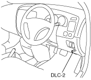
1. Connect the M-MDS to the DLC-2.
atraaw00000075
|
2. After the vehicle is identified, select the following items from the initial screen of the M-MDS.
3. Select the PID from the PID table.
4. Verify the PID data according to the directions on the screen.
PID/DATA MONITOR AND RECORD function table
|
Monitor item |
Definition |
Unit/Condition |
PCM terminal |
|---|---|---|---|
|
CCS
|
3-2 timing/coast clutch solenoid
|
On/Off
|
20
|
|
kPa
|
20
|
||
|
CCSV
|
3-2 timing/coast clutch solenoid control signal voltage
|
V
|
20
|
|
EPC
|
Electronic presser control solenoid
|
kPa
|
81
|
|
EPCV
|
Electronic presser control solenoid control signal voltage
|
V
|
81
|
|
GEAR
|
Selected gear (Calculated from shift solenoids A and B)
|
1/2/3/4
|
–
|
|
GEAR_MAX
|
No.1 gear candidate
|
–
|
–
|
|
GEAR_RAT
|
Gear ratio
|
–
|
–
|
|
OSS
|
Output shaft speed
|
RPM
|
84
|
|
OSS_SRC
|
Output shaft speed
|
RPM
|
84
|
|
SSA/SS1
|
Shift solenoid A
|
On/Off
|
6
|
|
SSA/SS1_F
|
Shift solenoid A status
|
Yes Fault/No Fault
|
–
|
|
SSB/SS2
|
Shift solenoid B
|
On/Off
|
11
|
|
SSB/SS2_F
|
Shift solenoid B status
|
Yes Fault/No Fault
|
–
|
|
TC_SLIPACT
|
Actual torque converter slip value
|
RPM
|
–
|
|
TC_SLIPDSD
|
Expected torque converter slip value
|
RPM
|
–
|
|
TCC
|
Torque converter clutch control solenoid
|
%
|
54
|
|
Engaged/Modulated/OFF
|
54
|
||
|
TCC_F
|
Torque converter clutch control solenoid status
|
Yes Fault/No Fault
|
–
|
|
TCC_RAT
|
Transaxle slip ratio
|
–
|
–
|
|
TCIL
|
O/D OFF indicator light
|
On/Off
|
–
|
|
TCS
|
O/D OFF switch
|
Not Depressed/Depressed
|
29
|
|
TFT
|
Transaxle fluid temperature
|
°C
|
37
|
|
V
|
37
|
||
|
TFT_F
|
Transaxle fluid temperature status
|
Yes Fault/No Fault
|
37
|
|
TR
|
Transaxle range
|
D/R/OD/
Man 2/Man 1/
P/N
|
64
|
|
TR_F
|
Transaxle range status
|
Yes Fault/No Fault
|
64
|
|
TR_V
|
Transaxle range signal voltage
|
V
|
64
|
|
TRAN_RAT
|
Transaxle gear ratio
|
–
|
–
|
|
TSS
|
Turbine shaft speed
|
RPM
|
59
|
|
TSS/ISS
|
Input shaft speed
|
RPM
|
59
|
|
TSS_SRC
|
Turbine shaft speed
|
RPM
|
59
|
|
TSSFM
|
TSS sensor failure mode
|
Yes Fault/No Fault
|
59
|
Simulation Function Procedure
1. Connect the M-MDS to the DLC-2.
atraaw00000075
|
2. After the vehicle is identified, select the following items from the initial screen of the M-MDS.
3. Select the simulation items from the PID table.
4. Perform the simulation function, inspect the operations for each parts.
Simulation item table
|
Simulation item |
Applicable component |
Unit/Condition |
PCM terminal |
|---|---|---|---|
|
CCS
|
3-2 timing/coast clutch solenoid
|
On/Off
|
20
|
|
kPa
|
20
|
||
|
EPC
|
Electronic presser control solenoid
|
kPa
|
81
|
|
SSA/SS1
|
Shift solenoid A
|
On/Off
|
6
|
|
SSB/SS2
|
Shift solenoid B
|
On/Off
|
11
|
|
TCC
|
Torque converter clutch control solenoid
|
%
|
54
|
|
Engaged/Modulated/OFF
|
54
|