DTC P0712, P0713, P1713, P1718[LA4AX-EL (CD4E)]
id050207806000
DTC P0712 |
Transaxle fluid temperature (TFT) sensor circuit malfunction (short to ground) |
---|---|
DTC P0713 |
Transaxle fluid temperature (TFT) sensor circuit malfunction (open circuit/short to power supply) |
DTC P1713 |
ATF signal stuck at low temperature. |
DTC P1718 |
ATF signal stuck at high temperature. |
DETECTION CONDITION
|
• P0712: PCM detects that ATF signal output from ATF sensor is 150° C {302° F} or more
• P0713: PCM detects ATF signal from ATF sensor is–40° C {–40° F} or less
• P1713: ATF signal from ATF sensor does not change from –40° C {–40° F} or less
• P1718: ATF signal from ATF sensor does not change from 150° C {302° F} or more
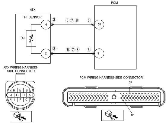
|
POSSIBLE CAUSE
|
• TFT sensor malfunction
• Short to ground in wiring harness between TFT sensor and ATX terminal E
• Short to ground in wiring harness between TFT sensor and ATX terminal H
• Short to ground in wiring harness between ATX terminal E and PCM terminal 91
• Short to ground in wiring harness between ATX terminal H and PCM terminal 37
• Open circuit in wiring harness between TFT sensor and ATX terminal E
• Open circuit supply in wiring harness between TFT sensor and ATX terminal H
• Open circuit supply in wiring harness between ATX terminal E and PCM terminal 91
• Open circuit supply in wiring harness between ATX terminal H and PCM terminal 37
• Short to power supply in wiring harness between TFT sensor and ATX terminal E
• Short to power supply in wiring harness between TFT sensor and ATX terminal H
• Short to power supply in wiring harness between ATX terminal E and PCM terminal 91
• Short to power supply in wiring harness between ATX terminal H and PCM terminal 37
• Damaged connectors between TFT sensor and PCM
• PCM malfunction
|
![]() |
Diagnostic procedure
STEP |
INSPECTION |
ACTION |
|
---|---|---|---|
1
|
VERIFY FREEZE FRAME DATA HAS BEEN RECORDED
• Has the FREEZE FRAME DATA been recorded?
|
Yes
|
Go to the next step.
|
No
|
Record the FREEZE FRAME DATA on the repair order, then go to the next step.
|
||
2
|
VERIFY RELATED SERVICE INFORMATION AVAILABILITY
• Verify related Service Information availability.
• Is any related Service Information available?
|
Yes
|
Perform repair or diagnosis according to the available Service Information.
• If the vehicle is not repaired, go to the next step.
|
No
|
Go to the next step.
|
||
3
|
INSPECT ATX CONNECTOR FOR POOR CONNECTION
• Turn the ignition switch to the LOCK position.
• Inspect ATX connector connection.
• Disconnect the ATX connector.
• Inspect for poor connection (such as damaged/pulled-out pins, corrosion).
• Is the connection normal?
|
Yes
|
Go to the next step.
|
No
|
Repair or replace the connector and/or terminals, then go to Step 9.
|
||
4
|
INSPECT TFT SENSOR
• Inspect the TFT sensor.
• Is TR switch normal?
|
Yes
|
Go to the next step.
|
No
|
Replace the TFT sensor, then go to Step 9.
|
||
5
|
INSPECT PCM CONNECTOR FOR POOR CONNECTION
• Disconnect the PCM connector.
• Inspect for poor connection (such as damaged/pulled-out pins, corrosion).
• Is the connection normal?
|
Yes
|
Go to the next step.
|
No
|
Repair or replace the connector and/or terminals, then go to Step 9.
|
||
6
|
INSPECT TFT SENSOR CIRCUIT FOR SHORT TO GROUND
• Inspect for continuity between ATX terminals (wiring harness-side) and body ground.
• Is there continuity?
|
Yes
|
Repair or replace the wiring harness, then go to Step 9.
|
No
|
Go to the next step.
|
||
7
|
INSPECT TFT SENSOR CIRCUIT FOR OPEN CIRCUIT
• Inspect the following ATX terminals (wiring harness-side) and PCM terminals (wiring harness-side):
• Is there continuity?
|
Yes
|
Go to the next step.
|
No
|
Repair or replace the wiring harness, then go to Step 9.
|
||
8
|
INSPECT TFT SENSOR CIRCUIT FOR SHORT TO POWER SUPPLY
• Turn the ignition switch to the ON position (engine off).
• Inspect the voltage at ATX terminals E and H (wiring harness-side).
• Is the voltage 0 V?
|
Yes
|
Go to the next step.
|
No
|
Repair or replace the wiring harness, then go to the next step.
|
||
9
|
VERIFY TROUBLESHOOTING OF DTC P0712, P0713, P1713 OR P1718 COMPLETED
• Make sure to reconnect all the disconnected connectors.
• Clear the DTC from the memory using the M-MDS.
• Perform the “After Repair Procedure”.
• Is the same DTC present?
|
Yes
|
Replace the PCM, then go to the next step.
|
No
|
Go to the next step.
|
||
10
|
VERIFY DTCS
• Are except DTC P0712, P0713, P1713 and P1718 output?
|
Yes
|
Go to the applicable DTC inspection.
(See DTC TABLE[LA4AX-EL (CD4E)].)
|
No
|
DTC troubleshooting completed.
|