atraaw00001901
|
MECHANICAL SYSTEM TEST[GF4AX-EL]
id051703802100
Mechanical System Test Preparation
1. Engage the parking brake and use wheel chocks at the front and rear of the wheels.
2. Inspect the engine coolant level. (See COOLING SYSTEM SERVICE WARNINGS[L3].) (See ENGINE COOLANT LEVEL INSPECTION[L3].)
3. Inspect the engine oil level. (See ENGINE OIL LEVEL INSPECTION[L3].)
4. Inspect the ATF level. (See AUTOMATIC TRANSAXLE FLUID (ATF) INSPECTION[GF4AX-EL].)
5. Inspect the ignition timing. (See ENGINE TUNE-UP[L3].)
6. Inspect the idle speed. (See ENGINE TUNE-UP[L3].)
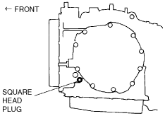
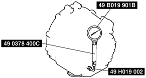
Line Pressure Test
1. Engine idling.
atraaw00001901
|
atraaw00001902
|
|
Position/Range |
Line pressure (kPa {kgf/cm2, psi}) |
|---|---|
|
Idle |
|
|
D, 2, 1
|
412—539 {4.2—5.4, 60—78}
|
|
R
|
726—1,010 {7.4—10.2, 106—146}
|
2. Engine stall speed.
|
Position/Range |
Line pressure (kPa {kgf/cm2, psi}) |
|---|---|
|
Stall |
|
|
D, 2, 1
|
1,099—1,176 {11.2—11.9, 160—170}
|
|
R
|
1,903—2,029 {19.4—20.6, 276—294}
|
Evaluation of line pressure test
|
Line pressure |
Possible cause |
|---|---|
|
Low pressure in all ranges
|
• Worn oil pump
• Oil leaking from oil pump, control valve body, and/or transaxle case
• Pressure regulator valve sticking
• Pressure control solenoid malfunction
• Pressure modulator valve sticking
• Solenoid reducing valve sticking
|
|
Low pressure in D and 2 only
|
• Oil leaking from hydraulic circuit of forward clutch
|
|
Low pressure in 1 and R only
|
• Oil leaking from hydraulic circuit of low and reverse brake
|
|
Low pressure in R only
|
• Oil leaking from hydraulic circuit of reverse clutch
|
|
High pressure in all ranges
|
• Pressure control solenoid malfunction
• Pressure regulator valve sticking
• Pressure modulator valve sticking
• Pressure reducing valve sticking
|
Stall Speed Test
1. Perform mechanical system test preparation. (See Mechanical System Test Preparation.)
2. Start the engine.
3. Shift the selector lever to D range.
4. Firmly depress the brake pedal with the left foot, and gently depress the accelerator pedal with the right foot.
5. When the engine speed no longer increases, quickly read the engine speed and release the accelerator pedal.
6. Shift the selector to N position and let the engine idle for 1 min or more to cool the ATF.
7. Perform a stall test of the 2, 1 range and R position in the same manner as in Steps 3—6.
|
Position/Range |
Engine stall speed (rpm) |
|---|---|
|
D, 2, 1
|
2,000—2,500
|
|
R
|
8. Turn off the engine.
Evaluation of stall test
|
Condition |
Possible cause |
||
|---|---|---|---|
|
Above specification
|
In all forward ranges and R position
|
Insufficient line pressure
|
• Worm oil pump
|
|
• Oil leaking from oil pump, control valve, and/or transaxle case
|
|||
|
• Pressure regulator valve sticking
|
|||
|
• Pressure control solenoid malfunction
|
|||
|
• Pressure modulator valve sticking
|
|||
|
In forward ranges
|
• Forward clutch slipping
• One‐way clutch 1 slipping
|
||
|
In D ranges
|
• One‐way clutch 2 slipping
|
||
|
In 2 ranges
|
• 2-4 brake band slipping
|
||
|
In 1 range and R position
|
• Low and reverse brake slipping
|
||
|
In R position
|
• Low and reverse brake slipping
• Reverse clutch slipping
• Perform road test to determine whether problem is low and reverse brake or reverse clutch
|
||
|
Below specification
|
• Engine out of tune
|
||
|
• One‐way clutch slipping within torque converter
|
|||
Time Lag Test
1. Perform mechanical system test preparation. (See Mechanical System Test Preparation.)
2. Start the engine.
3. Warm up the engine until the ATF temperature reaches 60—70°C {140—158°}.
4. Shift the selector lever from N position to D range.
5. Use a stopwatch to measure the time it takes from shifting until engagement is felt. Take three measurements for each test and average the results using the following formula.
6. Perform the test for the following shifts in the same manner.
Evaluation of time lag test
|
Condition |
Possible Cause |
|
|---|---|---|
|
More than specification
|
N → D shift
|
• Insufficient line pressure
• Forward clutch slipping
• One‐way clutch 1 slippage
• One‐way clutch 2 slippage
|
|
N → R shift
|
• Insufficient line pressure
• Low and reverse brake slipping
• Reverse clutch slippage
|
|