SAS CONTROL MODULE REMOVAL/INSTALLATION
id081000801400
Removal
-
Warning
-
• Always wear safety glasses when repairing an air bag equipped vehicle and when handling an air bag module. This will reduce the risk of injury in the event of an accidental operation (deployment).
• After operation (deployment), the air bag surface can contain deposits of sodium hydroxide, a product of the gas generating combustion that is irritating to the skin. Wash your hands with soap and water afterward.
• Never probe the connectors on the air bag module with a tester. If it is probed directly, the deployment of the air bag could result in personal injury.
• The direction of the SAS control module installation is critical for proper air bag system operation (deployment). If a vehicle equipped with an air bag system has been involved in a collision in which the center tunnel area has been damaged, inspect the mounting and bracket for deformation. If damaged, the SAS control module must be replaced whether or not the air bags have operated (deployed). In addition, make sure the area of the SAS control module is restored to its original condition.
• The air bag sensor is important for proper air bag system operation. If a vehicle equipped with an air bag is involved in a collision, inspect the sensor mounting bracket and wiring harness connectors for deformation. Replace and properly position the sensor or any other damaged structural components whether or not the air bag has operated (deployed).
• To avoid accidental deployment of the air bag and possible personal injury, always deplete the back-up power supply before repairing or replacing any front or side air bag structural component, and before servicing, replacing, adjusting, or causing impact to components near the air bag sensors, such as doors, dashboard, console, door latches, strikers, seats and bonnet latches.
• Before servicing, refer to this workshop manual to determine the location of the crash zone sensor.
• The side air bag sensors are located at or near the base of the B-pillar.
• To deplete the backup power supply, disconnect the battery negative cable and wait for 1 min or more. Be sure to disconnect auxiliary batteries and power supplies (if equipped).
-
Caution
-
• Electronic modules are sensitive to static electrical charges. If exposed to these charges, damage can result.
-
Note
-
• Replace only with new parts. If the new part does not correct the malfunction, install the original part and perform the diagnostic procedure again.
All The Vehicles
1. Disconnect the negative battery cable and wait 1 min or more.
-
Warning
-
• The SST (diagnostic simulator) is for air bag system servicing only. Before using the vehicle, it must be removed. Failure to remove it could result in personal injury and loss of vehicle safety standards.
-
Note
-
• If a seat equipped with a seat mounted side air bag or a pre-tensioner front buckle (if equipped) is being serviced, the air bag system must be deactivated.
• The SST (diagnostic simulator) must be installed under the seats in the side air bag and pre-tensioner front buckle (if equipped) to floor connectors.
• Diagnostics or repairs are not to be performed on a side air bag system or a pre-tensioner front buckle (if equipped) with the seats in the vehicle. Prior to attempting to diagnose/repair the side air bag system or a pre-tensioner (if equipped) system the seats must be removed from the vehicle and the SST (diagnostic simulator) must be installed in the side air bag and the pre-tensioner front buckle (if equipped) connectors at the floor connectors. Remove the SST (diagnostic simulator) before operating the vehicle on the road.
• Diagnostics may be performed on seat systems other than the side air bag or pre-tensioner front buckle (if equipped) (lumbar, climate control, heat, power seat track) with the seat installed in the vehicle as long as the restraint system diagnostic tools are installed under the seats in the side air bag and pre-tensioner front buckle to floor connectors.
• After diagnosing/repairing the seat system, always remove the SST (diagnostic simulator) before operating the vehicle on the road.
2. Disconnect the driver-side air bag module connector.
3. Attach the SST (diagnostic simulator) to the clock spring connector at the top of the steering column.
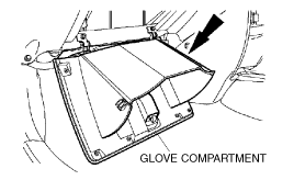
4. Fully open the glove compartment.
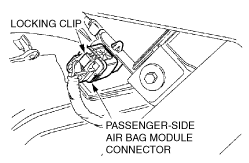
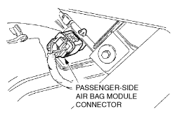
5. Disconnect the passenger-side air bag module outer connector through the glove compartment opening.
- (1) Push to release the passenger-side air bag module connector locking clip.
-
- (2) Disconnect the passenger-side air bag module connector.
-
6. Attach the SST (diagnostic simulator) to the vehicle wiring harness side of the passenger-side air bag connector.
7. Disconnect the passenger-side pre-tensioner front buckle connector.
8. Attach the SST (diagnostic simulator) to the passenger-side pre-tensioner front buckle floor connector.
Vehicles With Side Air Bags
1. Disconnect the passenger-side side air bag module connector.
2. Attach the SST (diagnostic simulator) to the passenger-side side air bag module floor connector.
All The Vehicles
1. Disconnect the driver-side pre-tensioner front buckle connector.
2. Attach the SST (diagnostic simulator) to the driver-side pre-tensioner front buckle floor connector.
Vehicles With Side Air Bags
1. Disconnect the driver-side side air bag module connector.
2. Attach the SST (diagnostic simulator) to the driver-side side air bag module floor connector.
All The Vehicles
1. Connect the negative battery cable.
2. With the SST (diagnostic simulator) installed to all deployable devices, diagnose the air bag system.
3. Disconnect the negative battery cable and wait 1 min or more.
4. Position the carpet back at the right-hand side of the center tunnel area under the dashboard.
5. Remove the right-hand side SAS control module nuts.
6. Position the carpet back at the left-hand side of the center tunnel area under the dashboard.
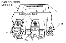
7. Remove the SAS control module.
- (1) Slide and disengage the two SAS control module connector locking clips.
-
- (2) Push down to pivot the SAS control module connector tabs and pull out to disconnect.
-
- (3) Remove the SAS control module nuts.
-
- (4) Remove the SAS control module.
-
Installation
-
Warning
-
• Always wear safety glasses when repairing an air bag equipped vehicle and when handling an air bag module. This will reduce the risk of injury in the event of an accidental operation (deployment).
• After operation (deployment), the air bag surface can contain deposits of sodium hydroxide, a product of the gas generating combustion that is irritating to the skin. Wash your hands with soap and water afterward.
• Never probe the connectors on the air bag module with a tester. If it is probed directly, the deployment of the air bag could result in personal injury.
• The direction of the SAS control module installation is critical for proper air bag system operation (deployment). If a vehicle equipped with an air bag system has been involved in a collision in which the center tunnel area has been damaged, inspect the mounting and bracket for deformation. If damaged, the SAS control module must be replaced whether or not the air bags have operated (deployed). In addition, make sure the area of the SAS control module is restored to its original condition.
• The air bag sensor is important for proper air bag system operation. If a vehicle equipped with an air bag is involved in a collision, inspect the sensor mounting bracket and wiring harness connectors for deformation. Replace and properly position the sensor or any other damaged structural components whether or not the air bag has operated (deployed).
• To avoid accidental deployment of the air bag and possible personal injury, always deplete the back-up power supply before repairing or replacing any front or side air bag structural component, and before servicing, replacing, adjusting, or causing impact to components near the air bag sensors, such as doors, dashboard, console, door latches, strikers, seats and bonnet latches.
• Before servicing, refer to this workshop manual to determine the location of the crash zone sensor.
• The side air bag sensors are located at or near the base of the B-pillar.
• To deplete the backup power supply, disconnect the battery negative cable and wait for 1 min or more. Be sure to disconnect auxiliary batteries and power supplies (if equipped).
-
Caution
-
• Electronic modules are sensitive to static electrical charges. If exposed to these charges, damage can result.
-
Note
-
• Replace only with new parts. If the new part does not correct the malfunction, install the original part and perform the diagnostic procedure again.
All The Vehicles
1. Position the SAS control module to the center tunnel area and tighten the three nuts by hand.
-
Warning
-
• To operate the system normally, tighten the SAS control module bolt to the specified torque.
• The SST (diagnostic simulator) is for air bag system servicing only. Before using the vehicle, it must be removed. Failure to remove it could result in personal injury and loss of vehicle safety standards.
-
Note
-
• If a seat equipped with a seat mounted side air bag or a pre-tensioner front buckle (if equipped) is being serviced, the air bag system must be deactivated.
• The SST (diagnostic simulator) must be installed under the seats in the side air bag and pre-tensioner front buckle (if equipped) to floor connectors.
• Diagnostics or repairs are not to be performed on a side air bag system or a pre-tensioner front buckle (if equipped) with the seats in the vehicle. Prior to attempting to diagnose/repair the side air bag system or a pre-tensioner front buckle (if equipped) the seats must be removed from the vehicle and the SST (diagnostic simulator) must be installed in the side air bag and the pre-tensioner front buckle (if equipped) connectors at the floor connectors. Remove the SST (diagnostic simulator) before operating the vehicle on the road.
• Diagnostics may be performed on seat systems other than the side air bag or pre-tensioner front buckle (if equipped) (lumbar, climate control, heat, power seat track) with the seat installed in the vehicle as long as the restraint system diagnostic tools are installed under the seats in the side air bag and pre-tensioner front buckle to floor connectors.
• After diagnosing/repairing the seat system, always remove the SST (diagnostic simulator) before operating the vehicle on the road.
2. Tighten the right side SAS control module nuts.
-
Warning
-
• The tightening torque of the air bag system is critical for proper system operation.
3. Reposition the carpet back at the right side of the center tunnel area under the dashboard.
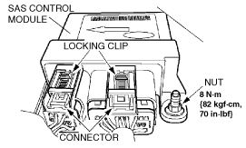
4. Connect the SAS control module.
-
Warning
-
• The tightening torque of the air bag system is critical for proper system operation.
- (1) Tighten the SAS control module nuts.
-
- (2) Connect the SAS control module connectors.
-
- (3) Slide and engage the SAS control module connector locking clips.
-
5. Reposition the carpet back at the left side of the center tunnel area under the dashboard.
6. Connect the negative battery cable.
7. With the SST (diagnostic simulator) installed to all deployable devices, diagnose the air bag system.
8. Disconnect the negative battery cable and wait 1 min or more.
9. Remove the SST (diagnostic simulator) from the driver-side pre-tensioner front buckle floor connector.
-
Warning
-
• The SST (diagnostic simulator) is for air bag system servicing only. Before using the vehicle, it must be removed. Failure to remove it could result in personal injury and loss of vehicle safety standards.
10. Connect the driver-side pre-tensioner front buckle connector.
Vehicles With Side Air Bags
1. Remove the SST (diagnostic simulator) from the passenger-side side air bag module connector.
-
Warning
-
• The SST (diagnostic simulator) is for air bag system servicing only. Before using the vehicle, it must be removed. Failure to remove it could result in personal injury and loss of vehicle safety standards.
2. Connect the driver-side side air bag module connector.
All The Vehicles
1. Remove the SST (diagnostic simulator) from the passenger-side pre-tensioner front buckle floor connector.
-
Warning
-
• The SST (diagnostic simulator) is for air bag system servicing only. Before using the vehicle, it must be removed. Failure to remove it could result in personal injury and loss of vehicle safety standards.
2. Connect the passenger-side pre-tensioner front buckle connector.
Vehicles With Side Air Bags
1. Remove the SST (diagnostic simulator) from the passenger-side side air bag module floor connector.
-
Warning
-
• The SST (diagnostic simulator) is for air bag system servicing only. Before using the vehicle, it must be removed. Failure to remove it could result in personal injury and loss of vehicle safety standards.
2. Connect the passenger-side side air bag module connector.
All The Vehicles
1. Remove the SST (diagnostic simulator) from the vehicle wiring harness side of the passenger-side air bag module connector.
-
Warning
-
• The SST (diagnostic simulator) is for air bag system servicing only. Before using the vehicle, it must be removed. Failure to remove it could result in personal injury and loss of vehicle safety standards.
2. Connect the passenger-side air bag module connector.
3. Close the glove compartment.
4. Remove the SST (diagnostic simulator) from the clock spring connector at the top of the steering column.
-
Warning
-
• The SST (diagnostic simulator) is for air bag system servicing only. Before using the vehicle, it must be removed. Failure to remove it could result in personal injury and loss of vehicle safety standards.
5. Connect the driver-side air bag module connector.
6. Connect the negative battery cable.
7. Verify that the SST (diagnostic simulator) is removed.
-
Warning
-
• The SST (diagnostic simulator) is for air bag system servicing only. Before using the vehicle, it must be removed. Failure to remove it could result in personal injury and loss of vehicle safety standards.