 |
atraaw00003229
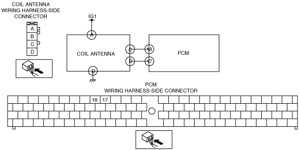
DTC B1681[IMMOBILIZER SYSTEM (PATS) (AJ (3.0L Duratec))]
id0902g3808200
Detection Condition
Possible Cause
atraaw00003229
|
Diagnostic Procedure
|
STEP |
INSPECTION |
ACTION |
|
|---|---|---|---|
|
1
|
INSPECT COIL ANTENNA POWER SUPPLY
• Disconnect the coil antenna connector.
• Turn the ignition switch to the ON position.
• Measure the voltage at coil antenna connector terminal A.
|
Yes
|
Go to the next step.
|
|
No
|
Repair the wiring harness.
|
||
|
2
|
INSPECT WIRING HARNESS BETWEEN COIL ANTENNA AND GROUND
• Turn the ignition switch to the LOCK position.
• Inspect the wiring harness between coil antenna connector terminal B and ground for the following items:
• Is the wiring harness normal?
|
Yes
|
Go to the next step.
|
|
No
|
Repair the wiring harness.
|
||
|
3
|
INSPECT COIL ANTENNA INPUT SIGNAL CIRCUIT
• Connect the coil antenna connector.
• Turn the ignition switch to the ON position.
• Measure the voltage at coil antenna connector terminal C.
|
Yes
|
Go to Step 7.
|
|
No
|
Go to the next step.
|
||
|
4
|
INSPECT COIL ANTENNA INPUT SIGNAL CIRCUIT
• Turn the ignition switch to the LOCK position.
• Disconnect the PCM connector.
• Turn the ignition switch to the ON position.
• Measure the voltage at PCM connector terminal 18.
|
Yes
|
Replace the PCM and perform the resetting procedure for the immobilizer system when replacing the PCM.
|
|
No
|
Go to the next step.
|
||
|
5
|
INSPECT COMMUNICATION CIRCUIT (INPUT) FOR CONTINUITY
• Turn the ignition switch to the LOCK position.
• Disconnect the coil antenna connector and PCM connector.
• Is there continuity between coil antenna connector terminal C and PCM connector terminal 18?
|
Yes
|
Go to the next step.
|
|
No
|
Repair the wiring harness.
|
||
|
6
|
INSPECT COIL ANTENNA INPUT SIGNAL CIRCUIT
• Measure the resistance between coil antenna connector terminal C and ground.
|
Yes
|
Replace the coil antenna.
|
|
No
|
Repair the wiring harness.
|
||
|
7
|
INSPECT COIL ANTENNA OUTPUT SIGNAL CIRCUIT
• Connect the coil antenna connector and PCM connector.
• Turn the ignition switch to the ON position.
• Measure the voltage at coil antenna connector terminal D.
|
Yes
|
Replace the coil antenna.
|
|
No
|
Go to the next step.
|
||
|
8
|
INSPECT COIL ANTENNA OUTPUT SIGNAL CIRCUIT
• Turn the ignition switch to the LOCK position.
• Disconnect the coil antenna connector.
• Turn the ignition switch to the ON position.
• Measure the voltage at coil antenna connector terminal D.
|
Yes
|
Replace the coil antenna.
|
|
No
|
Go to the next step.
|
||
|
9
|
INSPECT COMMUNICATION CIRCUIT (OUTPUT) FOR CONTINUITY
• Turn the ignition switch to the LOCK position.
• Disconnect the PCM connector.
• Is there continuity between coil antenna connector terminal D and PCM connector terminal 17?
|
Yes
|
Go to the next step.
|
|
No
|
Repair the wiring harness.
|
||
|
10
|
INSPECT COIL ANTENNA OUTPUT SIGNAL CIRCUIT
• Measure the resistance between PCM connector terminal 17 and ground.
|
Yes
|
Replace the PCM and perform the resetting procedure for the immobilizer system when replacing the PCM.
|
|
No
|
Repair the wiring harness.
|
||