|
1
|
INSPECT SJB POWER SUPPLY FUSES
• Are the SJB power supply fuses normal?
|
Yes
|
Go to the next step.
|
|
No
|
Install an appropriate amperage fuse.
|
|
2
|
INSPECT DOOR LATCH SWITCH INSTALLATION
• Are the door latch switches installed securely?
|
Yes
|
Go to the next step.
|
|
No
|
Install the door latch switches securely, then go back to Step 5 of KEYLESS ENTRY SYSTEM PRELIMINARY INSPECTION.
|
|
*3
|
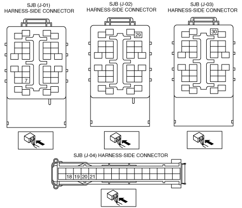
INSPECT IF MALFUNCTION IS IN WIRING HARNESS (NO CONTINUITY BETWEEN FUSE BLOCK AND SJB) OR ELSEWHERE
• Turn the ignition switch to the ON position.
• Measure the voltage at the following SJB terminals:
-
― IG1 signal (terminal J-01 7)
― Power supply signal (terminal J-02 29)
• Is the voltage B+?
|
Yes
|
Go to the next step.
|
|
No
|
Repair the wiring harness between the fuse block and SJB, then go to Step 8.
|
|
*4
|
INSPECT IF MALFUNCTION IS IN WIRING HARNESS (SHORT TO POWER SUPPLY BETWEEN FUSE BLOCK AND SJB, OR BETWEEN SJB AND GROUND) OR ELSEWHERE
• Turn the ignition switch to the LOCK position.
• Disconnect the SJB connector.
• Measure the voltage at the following SJB terminal (wiring harness-side):
-
― IG1 signal (terminal J-01 7)
• Is the voltage B+?
|
Yes
|
Repair the malfunctioning wiring harness, then go to Step 8.
|
|
No
|
Go to the next step.
|
|
*5
|
INSPECT IF MALFUNCTION IS IN WIRING HARNESS (NO CONTINUITY BETWEEN SJB AND GROUND) OR ELSEWHERE
• Is there continuity between SJB terminal J-03 30 and ground?
|
Yes
|
Go to the next step.
|
|
No
|
Repair the wiring harness between the SJB and ground, then go to Step 8.
|
|
6
|
INSPECT SJB OR WIRING HARNESS (BETWEEN SJB AND DOOR LATCH SWITCHES FOR CONTINUITY)
• Open all doors.
• Is there continuity between SJB terminals J-04 18, J-04 19, J-04 20, J-04 21 and ground?
|
Yes
|
Replace the SJB and reprogram the transmitter ID code, then go to the next step.
|
|
No
|
Repair the wiring harness between the SJB and door latch switches, then go to the next step.
|
|
7
|
INSPECT POWER SUPPLY FUSE
• Is the keyless control module power supply fuse normal?
|
Yes
|
Go to the next step.
|
|
No
|
Install an appropriate amperage fuse.
|
|
8
|
REINSPECT MALFUNCTION SYMPTOM AFTER REPAIR
• Does the keyless entry system operate properly?
|
Yes
|
Troubleshooting completed.
Explain repairs to the customer.
|
|
No
|
Reinspect the malfunction symptoms, then repeat from Step 1 if the malfunction recurs.
|