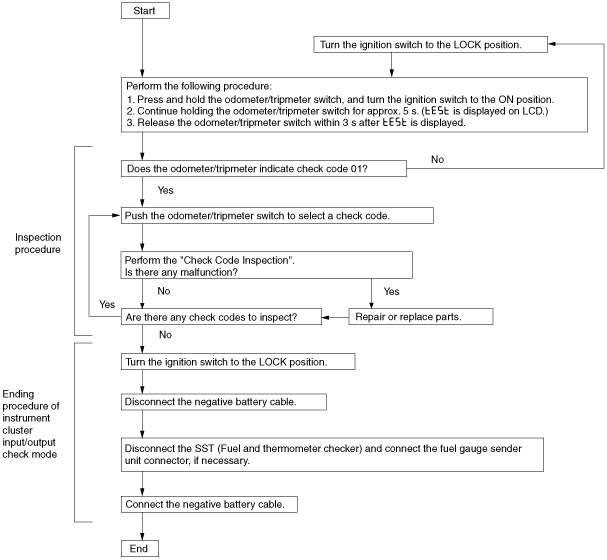
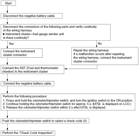
INPUT/OUTPUT CHECK MODE OF INSTRUMENT CLUSTER[L3]
id0922008002a6
Check Code Table
Check Code |
Check Item |
Related Item |
---|---|---|
01
|
Seat belt warning switch
|
Seat belt warning switch
|
04
|
Door switch
|
• Lights-on reminder warning alarm
• Key reminder warning alarm
|
08
|
TNS relay
|
• Lights-on reminder warning alarm
• Each illumination light
|
12
|
Speedometer
|
Speedometer
|
13
|
Tachometer
|
Tachometer
|
14
|
Buzzer
|
Buzzer
|
16
|
Fuel-level warning light
|
Fuel-level warning light
|
22
|
Fuel gauge sender unit (fuel pump unit)
|
Fuel gauge
|
23
|
Fuel gauge
|
Fuel gauge
|
25
|
Water temperature gauge
|
Water temperature gauge
|
26
|
Warning and indicator light controlled by odometer/tripmeter (LCD) and microcomputer
|
• Odometer/tripmeter
• Warning and indicator light
|
30
|
Ignition switch (ACC)
|
Ignition switch (ACC)
|
31
|
Key reminder switch
|
Key reminder warning alarm
|
55
|
Panel light control switch
|
Panel light control
|
56
|
SAS control module
|
Air bag warning alarm
|
atraaw00001932
|
Checking Order
Checking order |
Ignition switch position |
Check code |
---|---|---|
1
|
ON
|
22
|
2
|
01, 04, 08, 12, 13, 14, 16, 23, 25, 26, 55, 56
|
|
3
|
LOCK
|
30, 31
|
Check Code Inspection
Check code 01
Check code 01 |
Seat belt warning switch ON/OFF signal |
|||
---|---|---|---|---|
Step |
Inspection condition |
Display |
Action |
|
1
|
Driver-side seat belt is unbuckled. (Seat belt retractor switch is ON)
|
![]() |
Go to the next step.
|
|
![]() |
Verify that the voltage of instrument cluster terminal 1K is 0 V.
• If the voltage is as specified, replace the instrument cluster.
• If the voltage is not as specified, inspect the following parts:
|
|||
2
|
Driver-side seat belt is buckled. (Seat belt retractor switch is OFF)
|
![]() |
Verify that the voltage of instrument cluster terminal 1K is B+.
• If the voltage is as specified, replace the instrument cluster.
• If the voltage is not as specified, inspect the following parts:
|
|
![]() |
Input signal to the instrument cluster is normal.
|
Check code 04
Check code 04 |
Door switch ON/OFF signal |
|||
---|---|---|---|---|
Step |
Inspection condition |
Display |
Action |
|
1
|
Open the front driver-side door. (Door switch ON)
|
![]() |
Close the front driver-side door, then go to the next step.
|
|
![]() |
Verify that the voltage of instrument cluster terminal 2L is 1.0 V or less.
• If the voltage is as specified, replace the instrument cluster.
• If the voltage is not as specified, inspect the following parts:
|
|||
2
|
Close the front driver-side door. (Door switch OFF)
|
![]() |
Verify that the voltage of instrument cluster terminal 2L is B+.
• If the voltage is as specified, replace the instrument cluster.
• If the voltage is not as specified, inspect the following parts:
|
|
![]() |
Input signal to the instrument cluster is normal.
|
Check code 08
Check code 08 |
TNS relay ON/OFF signal |
|||
---|---|---|---|---|
Step |
Inspection condition |
Display |
Action |
|
1
|
Turn the light switch to the TNS position. (TNS relay ON)
|
![]() |
Go to the next step.
|
|
![]() |
Verify that the voltage of instrument cluster terminal 3A is B+.
• If the voltage is as specified, replace the instrument cluster.
• If the voltage is not as specified, inspect the following parts:
|
|||
2
|
Turn the light switch off. (TNS relay OFF)
|
![]() |
Verify that the voltage of the instrument cluster terminal 3A is 1.0 V or less.
• If the voltage is as specified, replace the instrument cluster.
• If the voltage is not as specified, inspect the following parts:
|
|
![]() |
Input signal to the instrument cluster is normal.
|
Check code 12
Check code 12 |
Speedometer display signal |
||||
---|---|---|---|---|---|
Inspection condition |
Display |
Action |
|||
After selecting check code 12, wait for approx. 2 s.
|
![]() |
The speedometer needle moves full scale then returns to approx. 60 km/h.
|
The speedometer is normal.
|
||
Except above
|
Replace the instrument cluster.
|
||||
![]() |
—
|
Check code 13
Check code 13 |
Tachometer indicator signal |
|||
---|---|---|---|---|
Inspection condition |
Display |
Action |
||
After selecting check code 13, wait for approx. 2 s.
|
![]() |
The tachometer needle moves full scale then returns to approx. 3,000 rpm .
|
The tachometer is normal.
|
|
Except above
|
Replace the instrument cluster.
|
|||
![]() |
—
|
Check code 14
Check code 14 |
Buzzer operation signal |
|||
---|---|---|---|---|
Inspection condition |
Display |
Action |
||
After selecting check code 14, wait for approx. 2 s.
|
![]() |
The buzzer sounds.
|
The buzzer is normal.
|
|
The buzzer does not sound.
|
Replace the instrument cluster.
|
Check code 16
Check code 16 |
Fuel-level warning light flashing signal |
|||
---|---|---|---|---|
Inspection condition |
Display |
Action |
||
After selecting check code 16, wait for approx. 2 s.
|
![]() |
The fuel-level warning light flashes three times.
|
The fuel-level warning light is normal.
|
|
Except above
|
Replace the instrument cluster.
|
Check code 22
Preparation
atraaw00001938
|
Check code 22 |
Fuel level signal |
|||
---|---|---|---|---|
Step |
Inspection condition |
Display |
Action |
|
1
|
Select check code 22 with the fuel gauge sender unit connector disconnected.
|
![]() |
Go to the next step.
|
|
Except above
|
Go to the Step 6.
|
|||
2
|
Connect terminals 2I and 3Q of the instrument cluster.
|
![]() |
Go to the next step.
|
|
Except above
|
Go to the Step 6.
|
|||
3
|
Using the SST (Fuel and thermometer checker) or resistor, input 20 ohms between instrument cluster terminals 2I and 3Q.
|
![]() |
Go to the next step.
|
|
Except above
|
Go to the Step 6
|
|||
4
|
Using the SST (Fuel and thermometer checker) or resistor, input 60 ohms between instrument cluster terminals 2I and 3Q.
|
![]() |
Go to the next step.
|
|
Except above
|
Go to the Step 6
|
|||
5
|
Using the SST (Fuel and thermometer checker) or resistor, input 100 ohms between instrument cluster terminals 2I and 3Q.
|
![]() |
Inspect the fuel gauge sender unit.
|
|
Except above
|
Go to the next step.
|
|||
6
|
Inspect the wiring harness and connector between instrument cluster and fuel gauge sender unit.
• If there is any malfunction, repair or replace the wiring harness or connector.
• If there is no malfunction, replace the instrument cluster.
|
Check code 23
Check code 23 |
Fuel gauge operation signal |
|||
---|---|---|---|---|
Inspection condition |
Display |
Action |
||
After selecting check code 23, wait for approx. 2 s.
|
![]() |
The fuel gauge indicates status in the following order approx. every 2 s.
• F → 1/2 → E → F (fixed)
|
The fuel gauge is normal.
|
|
Except above
|
Replace the instrument cluster.
|
|||
![]() |
Replace the instrument cluster.
|
Check code 25
Check code 25 |
Water temperature gauge operation signal |
|||
---|---|---|---|---|
Inspection condition |
Display |
Action |
||
After selecting check code 25, wait for approx. 2 s.
|
![]() |
The water temperature gauge indicates status in the following order approx. every 2 s.
• H→Center→C→H (fixed)
|
The water temperature gauge is normal.
|
|
Except above
|
Replace the instrument cluster.
|
|||
![]() |
Replace the instrument cluster.
|
Check code 26
Check code 26 |
Odometer/tripmeter display signal |
|||
---|---|---|---|---|
Inspection condition |
Display |
Action |
||
Select check code 26.
|
![]() |
LCD display and warning and indicator light controlled by micro computer are illuminated.
• O/D OFF indicator light
• Malfunction indicator lamp
• ABS warning light
• Brake system warning light
• Generator warning light
|
Odometer/tripmeter is normal, and warning and indicator light is normal.
|
|
Except above
|
Replace the instrument cluster.
|
Check code 30
Check code 30 |
Ignition switch (ACC) ON/OFF signal |
|||
---|---|---|---|---|
Step |
Inspection condition |
Display |
Action |
|
1
|
Turn the ignition switch to the ACC position.
|
![]() |
Go to the next step.
|
|
![]() |
Verify that the voltage of instrument cluster terminal 3M is B+.
• If the voltage is as specified, replace the instrument cluster.
• If the voltage is not as specified, inspect the following parts:
|
|||
2
|
Turn the ignition switch off.
|
![]() |
Verify that the voltage of the instrument cluster terminal 3M is 1.0V or less.
• If the voltage is as specified, replace the instrument cluster.
• If the voltage is not as specified, inspect the following parts:
|
|
![]() |
Input signal to the instrument cluster is normal.
|
Check code 31
Check code 31 |
Key reminder switch ON/OFF signal |
|||
---|---|---|---|---|
Step |
Inspection condition |
Display |
Action |
|
1
|
Turn the light switch to the TNS position.
Remove the key from the steering lock and reinsert the key into the steering lock after selecting check code 31. (Key reminder switch switch ON)
|
![]() |
Go to the next step.
|
|
![]() |
Verify that the voltage of instrument cluster terminal 2Q is B+.
• If the voltage is as specified, replace the instrument cluster.
• If the voltage is not as specified, inspect the following parts:
|
|||
2
|
Remove the key from the steering lock. (Key reminder switch switch OFF)
|
![]() |
Verify that the voltage of instrument cluster terminal 2Q is 1.0 V or less.
• If the voltage is as specified, replace the instrument cluster.
• If the voltage is not as specified, inspect the following parts:
|
|
![]() |
Input signal to the instrument cluster is normal.
|
Check code 55
Check code 55 |
Panel light control switch signal |
|||
---|---|---|---|---|
Step |
Inspection condition |
Display |
Action |
|
1
|
Press and hold down the button (+) (panel light control switch).
|
![]() |
Go to the next step.
|
|
![]() |
Verify that the voltage of instrument cluster terminal 2K is 1.0 V or less.
• If the voltage is as specified, replace the instrument cluster.
• If the voltage is not as specified, inspect the following parts:
|
|||
2
|
Press and hold down the button (-) (panel light control switch).
|
![]() |
Go to the next step.
|
|
![]() |
Verify that the voltage of instrument cluster terminal 2K is 1—4 V.
• If the voltage is as specified, replace the instrument cluster.
• If the voltage is not as specified, inspect the following parts:
|
|||
3
|
Release the panel light control switch.
|
![]() |
Input signal to the instrument cluster is normal.
|
|
![]() |
• Disconnect the negative battery cable.
• Disconnect the instrument cluster connector.
• Verify that the continuity between the instrument cluster terminal 2K and body GND.
|
Check code 56
Check code 56 |
Air bag warning alarm ON/OFF signal |
|||
---|---|---|---|---|
Step |
Inspection condition |
Display |
Action |
|
1
|
Connect the M-MDS to the DLC-2.
Turn ON the simulation item "WRNLMPCHM" of the SAS control module.
|
![]() |
Go to the next step.
|
|
![]() |
Verify that the voltage of the instrument cluster terminal 2J is 1.0 V or less.
• If the voltage is as specified, replace the instrument cluster.
• If the voltage is not as specified, inspect the following parts:
|
|||
2
|
Turn OFF the simulation item "WRNLMPCHM" of the SAS control module.
|
![]() |
Verify that the voltage of instrument cluster terminal 2J is B+.
• If the voltage is as specified, replace the instrument cluster.
• If the voltage is not as specified, inspect the following parts:
|
|
![]() |
Input signal to the instrument cluster is normal.
|