|
acxuun00000506
MULTIPLEX COMMUNICATION SYSTEM CONSTRUCTION/OPERATION[L3]
id0940001004a5
CAN System-Related Module Construction
|
Component |
Function |
|
|---|---|---|
|
Power circuit
|
Supplies power to CPU and vicinity, and to input/output interface.
|
|
|
CPU
|
Computation processing block
|
In addition to conventional CPU function, when transmission is necessary, transmitted data is stored in a multiplex block.
When the multiplex block receives a request to read stored data, transmitted data is read from the multiplex block.
|
|
Multiplex block
|
Transmits data received from bus lines to computation processing block.
In addition, sends transmitted data stored from computation processing block to bus lines.
|
|
|
Input interface circuit
|
Converts information signals from switches to electrical signals that can be input to CPU.
|
|
|
Output interface circuit
|
Converts electrical signals output from CPU for operating motors and other parts.
|
|
acxuun00000506
|
Twisted Pair Construction
atraan00000372
|
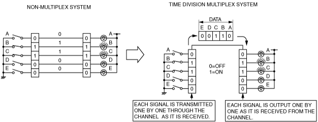
CAN System Outline
CAN System Operation
Time Division Multiplex
acxuun00000508
|
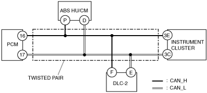
Vehicle CAN System
acxuun00000509
|
CAN Signal Table
|
Signal |
CAN system-related module |
||
|---|---|---|---|
|
PCM |
ABS HU/CM |
Instrument cluster |
|
|
Engine speed
|
OUT
|
―
|
IN
|
|
Vehicle speed
|
OUT
|
―
|
IN
|
|
Brake system warning light illumination request
|
―
|
OUT
|
IN
|
|
ABS warning light illumination request
|
―
|
OUT
|
IN
|
|
ECT
|
OUT
|
―
|
IN
|
|
Distance travelled
|
OUT
|
―
|
IN
|
|
Engine warning light illumination request
|
OUT
|
―
|
IN
|
|
O/D OFF indicator light illumination request
|
OUT
|
―
|
IN
|
|
Generator warning light illumination request
|
OUT
|
―
|
IN
|
|
Wheel speed (LF, RF, LR, RR)
|
IN
|
OUT
|
―
|
|
Engine specification
|
OUT
|
IN
|
―
|
ON-BOARD DIAGNOSTIC SYSTEM OUTLINE
On-Board Diagnostic System Construction/Operation
Block Diagram
aesffn00000114
|
Malfunction detection function
Fail-safe function
Memory function
Display function
DTC table
|
DTC |
Malfunction location |
DTC Output Unit |
|---|---|---|
|
U0073
|
Module communication error
|
• PCM
• Instrument cluster
|
|
U0121
|
Communication error
|
PCM
|
|
U1900
|
Communication error
|
• ABS HU/CM
• Instrument cluster
|
|
U2023
|
Abnormal data
|
ABS HU/CM
|
PID/data monitor function
|
Mazda Modular Diagnostic System (M-MDS) display |
Status |
Description |
Monitor module |
Terminal |
|---|---|---|---|---|
|
ABS_MSG
|
Present
|
Communication circuit between ABS HU/CM and monitor module is normal
|
Instrument cluster
|
3E, 3C
|
|
Not Present
|
Communication circuit between ABS HU/CM and monitor module is not normal
|
|||
|
PCM_MSG
|
Present
|
Communication circuit between PCM and monitor module is normal
|
||
|
Not Present
|
Communication circuit between PCM and monitor module is not normal
|
Malfunction Location Determination
Flowchart
atraan00000376
|
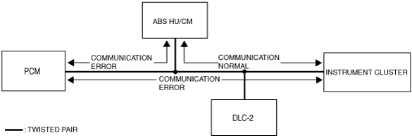
Example (PCM-related wiring harness open circuit)
1. DTCs for CAN system-related modules are verified using the Mazda Modular Diagnostic System (M-MDS).
|
Module |
DTC |
Probable malfunction location |
|---|---|---|
|
PCM
|
U0073
|
PCM-related CAN system malfunction
|
|
U0121
|
Communication error
|
|
|
ABS HU/CM
|
U2523
|
Communication error
|
|
Instrument cluster
|
U1900
|
Communication error
|
2. Instrument cluster PIDs are verified using the Mazda Modular Diagnostic System (M-MDS).
|
PID |
DTC |
Probable malfunction location |
|---|---|---|
|
PCM_MSG
|
Not Present
|
Communication error between the instrument cluster and the PCM
|
|
ABS_MSG
|
Present
|
Normal communication between instrument cluster and ABS HU/CM
|
aesffn00000115
|
3. If there is a communication error between the instrument cluster and PCM, even if the communication between the ABS HU/CM and the instrument cluster is normal, it is probable that there is a malfunction in the PCM or PCM-related wiring harnesses.