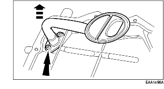
1. Remove the bolt and the oil level indicator and tube.
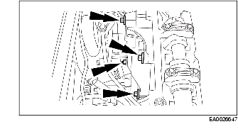
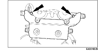
2. Remove the six bolts and three nuts and remove the exhaust manifold.
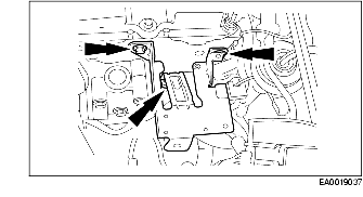
3. Remove the power steering pump bracket.
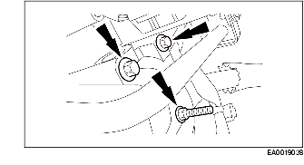
4. Remove the A/C compressor bracket.
5. Remove the coolant tube.
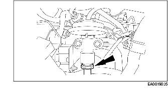
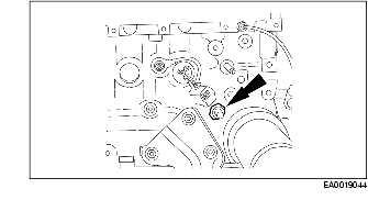
6. Remove the crankshaft position (CKP) sensor.
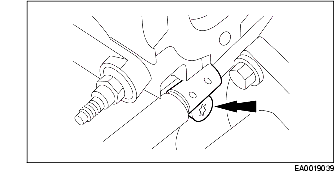
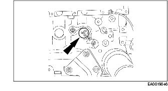
7. Remove the catalytic converter bracket.
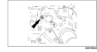
8. Remove the crankcase vent oil separator.
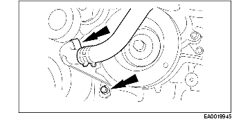
9. Remove the coolant tube.
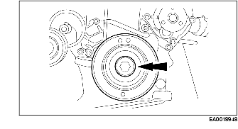
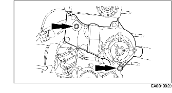
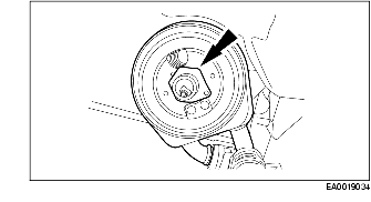
10. Remove the bolt and remove the crankshaft pulley.
11. Remove the accessory drive belt idler pulley.
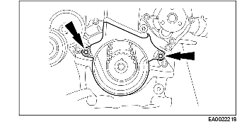
12. Remove the lower timing belt cover.
13. Remove the lower engine mount bracket.
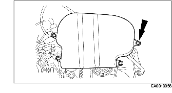
14. Remove the upper timing belt cover.
15. Remove the timing belt tensioner and the timing belt.
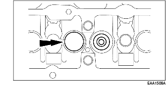
16. Remove the water pump adapter.
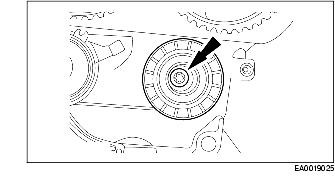
17. Remove the timing belt idler pulley.
18. Remove the ignition wires from the spark plugs.
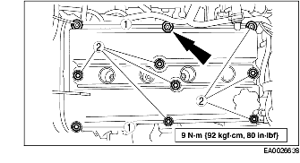
19. Remove the valve cover.
20. Remove the bolts and the camshaft timing sprockets.
21. Remove the camshafts.
22. Remove the valve tappets from the cylinder head.
23. Remove the inner timing belt cover.
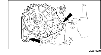
24. Remove the generator.
25. Remove the generator bracket.
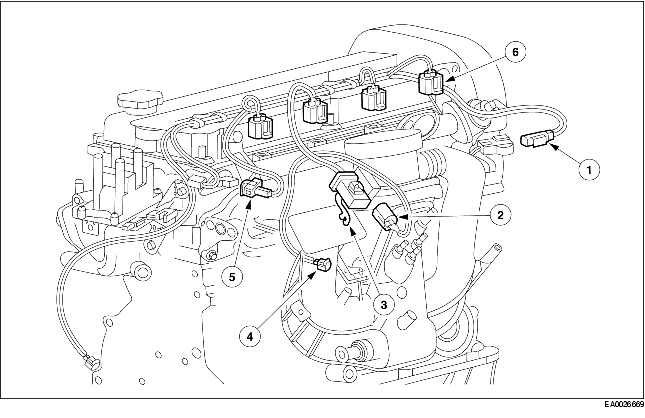
26. Disconnect the following electrical connectors and remove the fuel charging wiring harness from the engine:
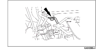
27. Disconnect EGR tube fitting.
28. Remove the EGR tube.
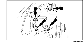
29. Remove the coil and bracket assembly.
30. Remove the thermostat housing.
31. Remove the PCV tube.
32. Remove the intake manifold.
33. Remove the oil pressure sensor.
34. Remove the block heater if equipped.
35. Remove the knock sensor.
36. Remove the oil cooler.
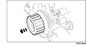
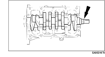
37. Remove the crankshaft sprocket and timing belt guide.
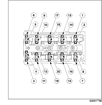
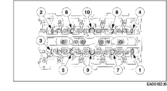
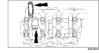
38. Remove the cylinder head using the sequence shown.
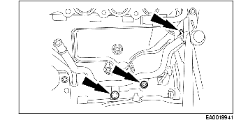
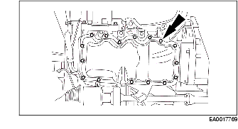
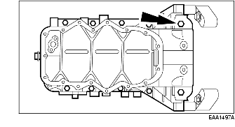
39. Remove the 17 bolts and the oil pan.
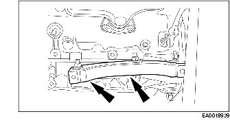
40. Remove the bolts and the oil pump cover and screen.
41. Remove the lower cylinder block and the gasket.
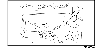
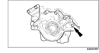
42. Remove the seven bolts and the oil pump.
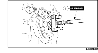
43. If equipped with manual transmission, use the SST to, remove the pilot bearing.
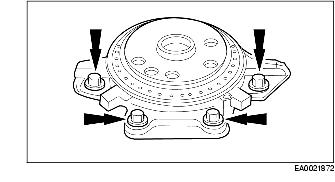
44. Remove the rear main oil seal retainer assembly and discard the gasket.
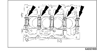
45. Remove the four connecting rod caps.
46. If the connecting rod bearings are to be reused, each one must be identified so that it can be installed in its original location. Remove the four upper and four lower connecting rod bearings.
47. Use a suitable tool and remove the cylinder ridge.
48. Remove the four piston and connecting rod assemblies.
49. Remove the bolts and remove the crankshaft main bearing caps and lower bearings.
50. Remove the crankshaft.
51. Remove the upper crankshaft main bearings.
52. Remove the Woodruff key.