1. Remove the bracket.
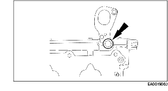
2. Remove the rear lifting eye.
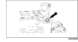
3. Remove the front lifting eye.
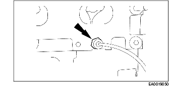
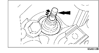
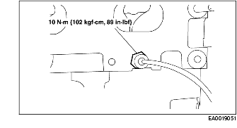
4. Remove the cylinder head temperature (ECT) sensor.
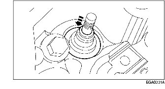
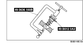
5. Using the SSTs, compress the valve spring and remove the valve spring retainer keys, the valve spring retainers, and the valve springs.
6. Inspect the valve spring, valve spring retainer and valve spring retainer key. For additional information. (See VALVE, VALVE GUIDE INSPECTION.) Install new parts as necessary.
7. Remove the valves.
8. Using the SSTs, remove and discard the valve stem seals.
9. Inspect the valves. For additional information. (See VALVE, VALVE GUIDE INSPECTION.) Install new parts as necessary.
1. Install the valves.
2. Lubricate valve and guides with engine oil and using the SST install the valve stem seals onto the cylinder head valve guides.
3. Place the valve spring in position over the valve and install the valve spring retainer.
4. Using the SSTs, compress the valve spring and install the valve spring retainer keys.
5. Install the ECT sensor.
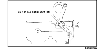
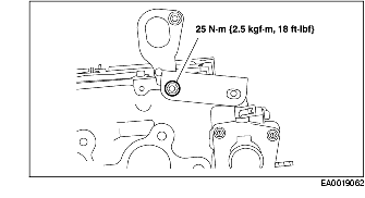
6. Install the front lifting eye.
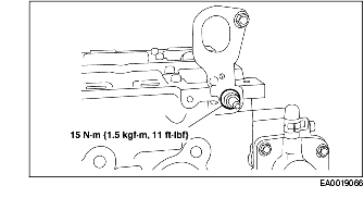
7. Install the rear lifting eye.
8. Install the bracket.
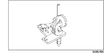
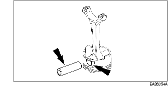
1. Use the Piston Pin Tool to press the piston pin out from the piston assembly and connecting rod.
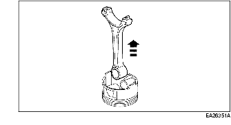
2. Remove the connecting rod and piston rings from the piston.
3. Clean and inspect the piston, piston pin and connecting rod. For additional information. (See PISTON, PISTON RING, PISTON PIN INSPECTION.)
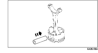
1. Lubricate the piston pin and piston pin bore.
2. Position the piston pin in the bore aligned with the connecting rod bore.
3. Use the Piston Pin Tool to press the piston pin into the piston and connecting rod assembly.
4. Fit and install the piston rings. For additional information. (See PISTON, PISTON RING, PISTON PIN INSPECTION.)