ASSEMBLY
BUE011002000E07
Engine
-
Warning
-
• Eye protection is required to be worn during use of compressed air. Failure to follow these instructions could result in possible personal injury.
-
Caution
-
• The engine sealing surfaces are soft metals. Do not use abrasive grinding discs to remove gasket material; only use manual scrapers. Do not scratch or gouge sealing surfaces or oil leaks may occur.
1. Clean and dry the cylinder block.
-
• Clean gasket material, dirt and foreign material from the cylinder block.
-
• Wash the cylinder block with a suitable soap and water solution.
-
• Dry the cylinder block completely using compressed air.
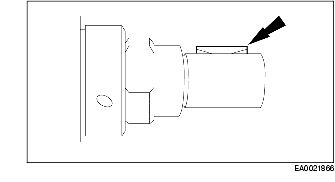
2. Install the Woodruff key.
3. Install the upper crankshaft main bearings, the upper crankshaft thrust main bearing and the lower crankshaft main bearings.
-
Note
-
• Apply engine oil to the crankshaft bearings and journals.
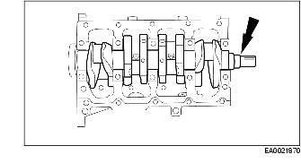
4. Position the crankshaft.
5. Determine crankshaft main bearing clearance. (See CRANKSHAFT INSPECTION/REPAIR.)
-
Caution
-
• Make sure the main bearing caps are installed in their original position or engine damage may occur.
-
Note
-
• Apply engine oil to the crankshaft bearings and journals.
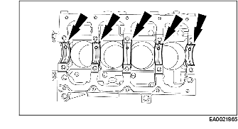
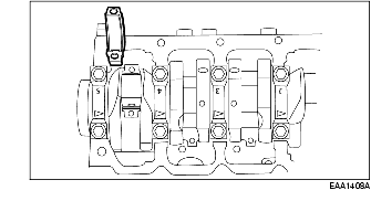
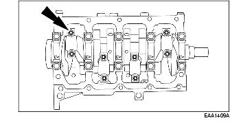
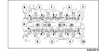
6. Install the main bearing caps.
7. Tighten the bolts using the sequence shown in two stages.
-
• Stage 1: Tighten the bolts to 25 N·m {2.5 kgf·m, 18 ft·lbf}.
-
• Stage 2: Tighten the bolts an additional 60 degrees.
8. Rotate the crankshaft and inspect for excessive drag or binding.
9. Inspect the crankshaft end play. For additional information. (See CRANKSHAFT INSPECTION/REPAIR.)
-
Caution
-
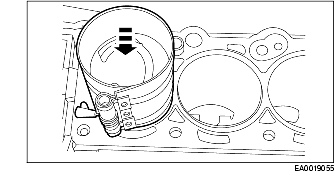
• PIP mark on pistons and squirt groove on connecting rods must be located on the intake side of the engine or possible engine damage may occur.
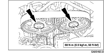
-
• Use care when installing piston and connecting rod assemblies. Do not scratch the cylinder walls or the crankshaft journals or engine damage may occur.
-
• The arrow on the piston must point toward the front of the engine or engine damage may occur.
-
Note
-
• Lubricate the cylinder block, piston rings and connecting rod prior to installation with engine oil.
10. Install the four piston and connecting rod assemblies.
-
Caution
-
• Connecting rods and connecting rod caps must be correctly oriented, the interlocking tangs on the same side of the connecting rod or possible engine damage may occur.
-
Note
-
• Turn the crankshaft each time to install the connecting rod caps.
11. Fit the connecting rod bearing.
-
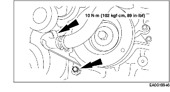
• Install the four upper and the four lower connecting rod bearings.
-
• Inspect the connecting rod bearing to the crankshaft clearance. (See CRANKSHAFT INSPECTION/REPAIR.)
-
Caution
-
• Connecting rods and connecting rod caps must be correctly oriented, the interlocking tangs on the same side of the connecting rod or possible engine damage may occur.
-
Note
-
• Lubricate the connecting rod bearings and the crankshaft journals prior to installation with engine oil.
-
• Rotate the crankshaft after installing each connecting rod cap and inspect for excess drag or binding.
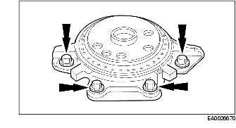
12. Install the connecting rod caps.
-
• Install new bolts and tighten in two stages:
-
• Stage 1: Tighten to 35 N·m {3.6 kgf·m, 26 ft·lbf}.
-
• Stage 2: Tighten an additional 90 degrees.
-
Note
-
• The clearance between the lower cylinder block sealing surfaces on the crankshaft rear oil seal retainer and the crankshaft cannot exceed 0.5 mm {0.02 in}.
13. Install a new gasket, the crankshaft rear oil seal retainer and tighten the bolts in two stages:
-
• Stage 1: Tighten to 12 N·m {1.2 kgf·m, 8.9 ft·lbf}.
-
• Stage 2: Tighten an additional 45 degrees.
-
Note
-
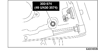
• Lubricate the crankcase flange and the crankshaft rear oil seal bore with engine oil to installing the crankshaft rear seal or damage to the crankshaft rear seal may occur.
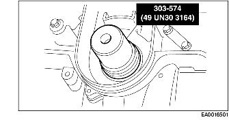
14. Using the SSTs, install a new crankshaft rear seal.
-
Note
-
• The clearance between the lower cylinder block sealing surfaces on the oil pump and the cylinder block cannot exceed 0.8 mm {0.031 in}.
15. Install a new gasket, the oil pump and tighten the bolts in two stages:
-
• Stage 1: Tighten to 6 N·m {62 kgf·cm, 53 in·lbf}.
-
• Stage 2: Tighten an additional 45 degrees.
-
Note
-
• Lubricate the crankcase flange and the crankshaft front oil seal bore with engine oil to installing the crankshaft front seal or damage to the crankshaft front seal may occur.
16. Using the SST, install a new crankshaft front seal.
-
Caution
-
• The lower engine block must be installed and the bolts tightened to specification within four minutes of sealant application or possible leakage may occur.
-
Note
-
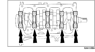
• Apply a 3 mm {0.1 in} bead of Silicone Gasket and Sealant in four places where the oil seal retainers meet the cylinder block.
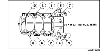
17. Install a gasket and the lower cylinder block. Tighten the bolts using the sequence shown.
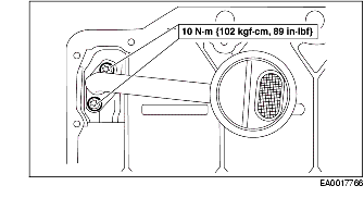
18. Install the oil pump cover and screen.
-
• Install new oil pump inlet tube gasket.
-
Note
-
• The oil pan must be installed and the bolts tightened to specification within seven minutes of sealer application or oil leaks may occur.
-
• Apply a 3 mm {0.1 in} continuous bead of Silicone Gasket and Sealant to the oil pan.
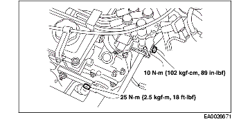
19. Install the oil pan. Tighten the bolts in two stages using the sequence shown.
-
• Stage 1: Tighten to 6 N·m {61 kgf·cm, 53 in·lbf}.
-
• Stage 2: Tighten to 12 N·m {1.2 kgf·m, 8.6 ft·lbf}.
-
Note
-
• Install a new pilot bearing on vehicles equipped with a manual transaxle only if it is damaged.
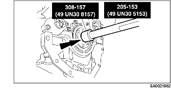
20. Using the SSTs, install the pilot bearing.
21. Install a new head gasket on the cylinder block.
-
Caution
-
• The bolts are torque-to-yield and new bolts must be installed or engine damage may occur.
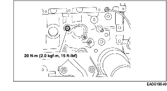
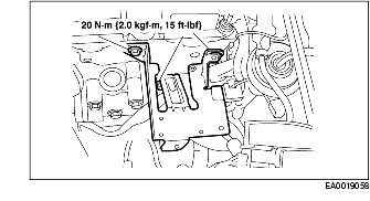
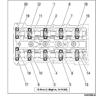
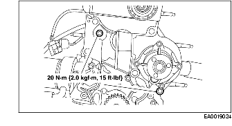
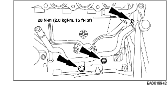
22. Install the cylinder head and tighten the bolts in three stages using the sequence shown.
-
• Stage 1: Tighten the bolts to 20 N·m {2.0 kgf·m, 15 ft·lbf}.
-
• Stage 2: Tighten the bolts to 40 N·m {4.1 kgf·m, 30 ft·lbf}.
-
• Stage 3: Tighten the bolts an additional 90 degrees.
23. Install the timing belt guide and crankshaft sprocket.
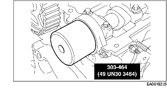
24. Install the oil cooler.
-
• Install a new oil cooler gasket.
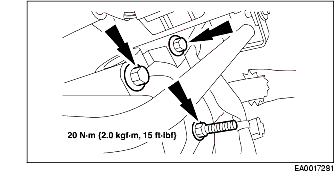
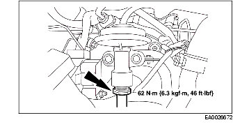
25. Install the knock sensor.
26. Install the block heater if equipped.
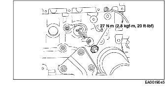
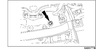
27. Install the oil pressure sensor.
-
Note
-
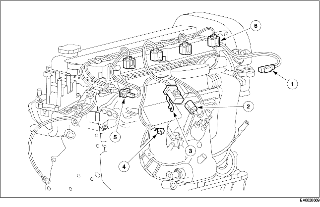
• Illustration shown with throttle body and fuel supply manifold removed for clarity.
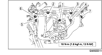
-
• Install new intake manifold gaskets if damaged.
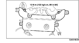
28. Install the intake manifold and tighten using the sequence shown.
29. Install the positive crankcase ventilation (PCV) tube.
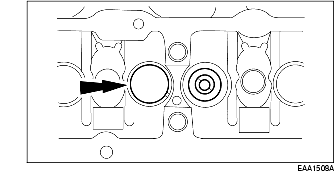
30. Install the thermostat housing.
-
• Install a new O-ring seal if damaged.
-
Note
-
• The coil shown removed for clarity.
31. Install the coil and coil bracket assembly.
32. Install the exhaust gas recirculation (EGR) tube.
33. Connect the EGR tube fitting.
34. Install the fuel charging wiring harness and connect the following electrical connectors:
-
(1) cylinder temperature sensor
-
(2) throttle position sensor
-
(3) wiring harness to vehicle
-
(4) idle air control valve
-
(5) camshaft position sensor
-
(6) fuel injectors
35. Install the generator bracket.
36. Install the generator.
37. Install the inner timing belt cover.
38. Loosely install the crankshaft pulley and rotate the crankshaft to just before top dead center (TDC) (No. 1 cylinder).
39. Remove the stud.
40. Install the SST.
-
Note
-
• Make sure the correct (second) notch in the pulley is indexed to the lower cylinder block.
41. Rotate the crankshaft clockwise against the peg to bring it to TDC (No. 1 cylinder).
-
• Remove the crankshaft pulley.
-
Caution
-
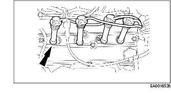
• If valve tappets are being reused the valve tappet must be installed in its original position or engine damage may occur.
-
Note
-
• Lubricate the valve tappets prior to installation with engine oil.
42. Install the valve tappets.
-
Note
-
• The front camshaft journal cap must be installed and the bolts tightened to specification within four minutes of sealer application or oil leaks may occur.
43. Coat the sealing surface of the front camshaft journal cap.
-
Note
-
• Lubricate the camshaft bearing surfaces with engine oil.
44. Install the camshafts.
-
• Position the camshafts and camshaft journal caps.
-
• Install the bolts and tighten the bolts in several two-turn passes using the sequence shown.
-
Note
-
• The exhaust camshaft oil seal is shown, the intake seal similar.
45. Using the SST, install new camshaft front oil seals.
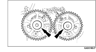
46. Install the camshaft sprockets and hand tighten the bolts.
-
• Rotate the camshafts one full turn and inspect them for binding.
47. Verify the valve clearance. For additional information, refer to Valve-Valve Clearance, Adjust in this section.
-
Caution
-
• The camshaft alignment tool is not recommended to hold the camshafts in place when removing or tightening the sprocket bolts. Damage to camshaft ears may result.
-
Note
-
• Installation of the alignment tool into the exhaust camshaft may require the camshaft to be rotated slightly.
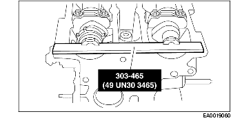
48. Install the SST onto the back of the camshafts.
49. Loosen the timing sprocket bolts and allow the camshaft sprockets to move freely.
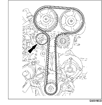
50. Install the timing belt idler pulley.
51. Install the water pump adapter.
-
• Install a new gasket.
-
Note
-
• Make sure the correct (second) notch in the pulley is indexed to the lower cylinder block.
52. Slide the crankshaft pulley onto the crankshaft and confirm the crankshaft position is at TDC (No. 1 cylinder) by rotating it clockwise against the alignment peg.
-
• Remove the crankshaft pulley.
53. Install the timing belt tensioner and the timing belt.
-
• Hand tighten the bolt.
54. Confirm that the timing belt tensioner is installed correctly with the tab positioned in the slot in the inner timing cover.
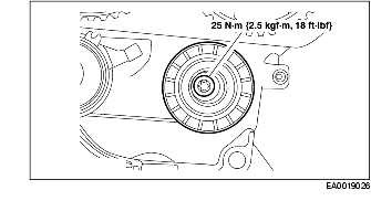
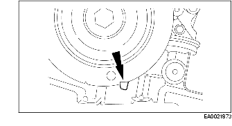
55. Adjust the timing belt tensioner.
-
(1) Using a 6mm Allen wrench, rotate the adjuster counterclockwise and align the marks as shown.
-
(2) Tighten the tensioner pulley bolt.
-
Warning
-
• The camshaft alignment tool is not recommended to hold the camshafts in place when removing or tightening the bolts. Damage to camshaft gears may result.
-
Note
-
• Use an open-end wrench to keep each camshaft from rotating.
56. Tighten the camshaft timing sprocket bolts to specifications.
57. Remove the SST.
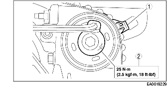
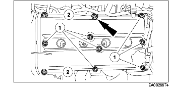
58. Install the bolts and the valve cover.
-
• Install the valve cover gasket.
-
(1) Install the bolts.
-
(2) Install the studbolts.
59. Connect the ignition wires to the correct spark plugs.
60. Install the timing belt upper cover.
61. Install the lower engine mount bracket.
62. Install the lower timing belt cover.
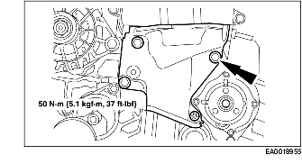
63. Install the accessory drive belt idler pulley.
-
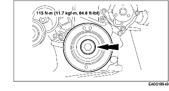
Note
-
• Apply Silicone Gasket and Sealant to the crankshaft pulley keyway prior to installing the crankshaft pulley.
64. Install the crankshaft pulley.
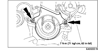
65. Install the coolant tube.
-
• Install the bolt.
-
• Connect the hose.
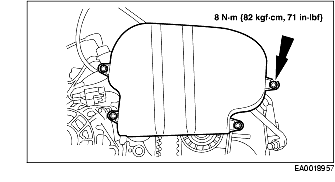
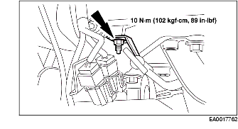
66. Install the crankcase vent oil separator.
-
(1) Install the bolts.
-
• Install a new gasket.
-
(2) Connect the PCV valve.
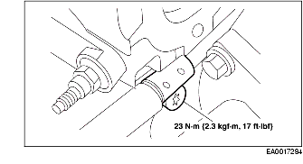
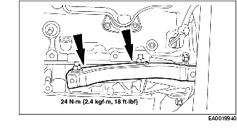
67. Install the catalytic converter bracket.
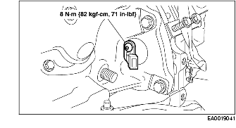
68. Install the crankshaft position sensor and bushing.
69. Install the stud.
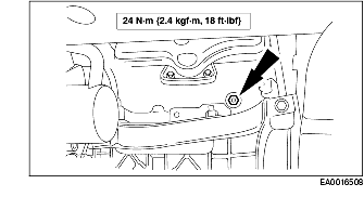
70. Install the coolant tube.
-
• Install the bolt and nut.
-
• Connect the hose.
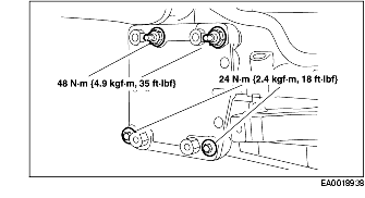
71. Install the A/C compressor bracket.
72. Install the power steering pump bracket.
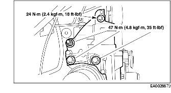
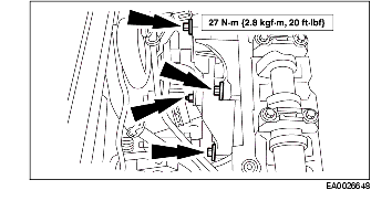
73. Install the exhaust manifold and tighten using the sequence shown.
-
• Install a new gasket.
74. Install the oil level indicator and tube.
-
• Install a new O-ring seal if damaged.