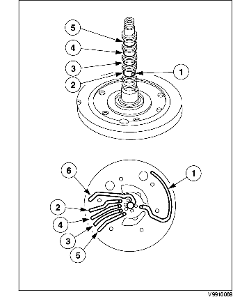
PUMP COMPONENT REMOVAL/INSTALLATION
BUE051700000113
Removal
.
|
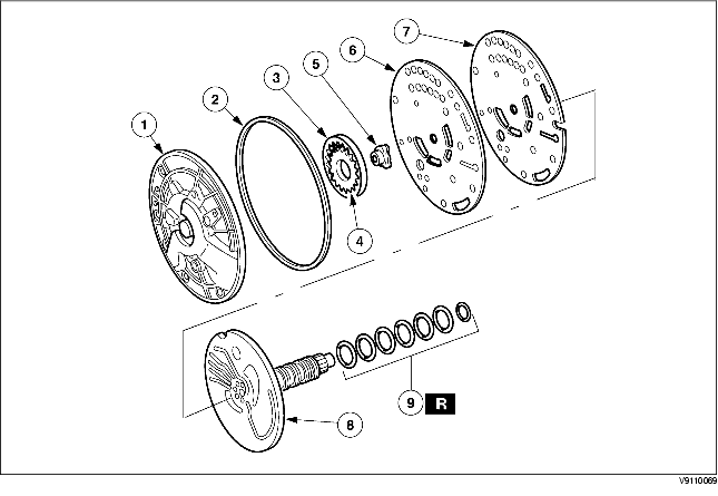
1
|
Pump body
|
|
2
|
O-ring
|
|
3
|
Driven gear
|
|
4
|
Drive gear
|
|
5
|
Drive gear insert
|
|
6
|
Separator plate
|
|
7
|
Separator plate gasket
|
|
8
|
Pump support
|
|
9
|
Pump seals
|
1. Remove and discard the seven pump support seal rings from the pump support.
2. Remove the six pump support bolts.
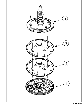
3. Separate the pump support and body component.
-
(1) Remove the pump support.
-
(2) Remove the pump body separator plate gasket.
-
(3) Remove the pump body separator plate.
-
(4) Remove the pump body.
4. Remove and discard the pump seal.
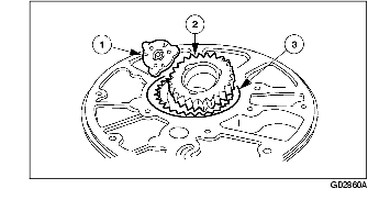
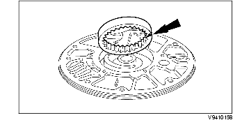
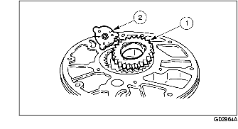
5. Remove the pump drive gear component.
-
(1) Pump drive gear insert.
-
(2) Pump drive gear.
-
(3) Pump driven gear.
6. Clean all parts thoroughly in clean solvent and blow dry with moisture-free regulated compressed air.
-
Warning
-
• Air pressure must not exceed 138 kPa {1.4 kgf/cm2, 20 psi}. Wear safety glasses when using compressed air. Failure to follow these instructions can result in personal injury.
7. Inspect the pump body and gears for damage and wear.
-
• Driven gear teeth
-
• Drive gear teeth
-
• Gear bore
-
• Crescent
-
• Lubrication passages and holes
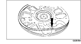
8. Inspect the pump support apply circuit passages and lubrication passages.
-
(1) Rear lubrication passage (from cooler TC circuit)
-
(2) Reverse clutch
-
(3) Direct clutch
-
(4) Forward clutch
-
(5) Coast clutch
-
(6) Converter clutch bypass
Installation
1. Install the pump driven gear.
-
Note
-
• The identification dot on the pump driven gear must face downward.
2. Install the pump drive gear component.
-
(1) Install the pump drive gear.
-
(2) Install the pump drive gear insert.
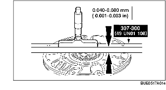
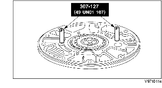
3. Using the SST, measure the clearance between each gear and the pump body face.
-
• If the clearance exceeds specification, install a new pump component.
4. Install the SST.
5. Align the pump support component. Fill the pump gear cavity with ATF to the top of the gears. Align the pump guide screws.
-
(1) Install the pump body.
-
(2) Install the pump body separator plate.
-
(3) Install the pump body separator plate gasket onto the pump body.
-
(4) Install the pump support.
6. Install the six pump support bolts.
-
Note
-
• Install the four pump support bolts in the pump support holes, and remove the SST. Then install the last two bolts.
7. Install the new pump seal on the pump body.
-
Note
-
• Make sure that the white stripe on the pump seal is visible around the pump body circumference.
8. Install the seven pump support seal rings.
-
Note
-
• Make sure the pump support seal rings are overlapped correctly.
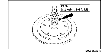
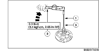
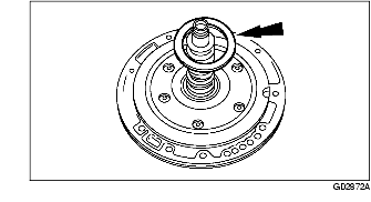
9. Measure the pump rotational torque.
-
(1) Install the pump drive shaft.
-
(2) Measure the pump rotational torque.
-
(3) Remove the pump drive shaft.
-
• If rotational torque exceeds the specification, disassemble and inspect the pump component for contamination or incorrect end clearance.
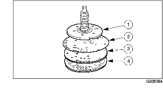
10. Install the No.1 pump support thrust bearing.
-
• Lubricate the seal rings with clean ATF.
11. Install the forward/coast/direct clutch cylinder and reverse clutch drum on the pump support.
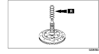
12. Inspect the following passages of the forward/coast/direct clutch cylinder and reverse clutch drum with moisture-free compressed air, regulated to 138 kPa {1.4 kgf/cm2, 20 psi}.
-
Warning
-
• Air pressure must not exceed 138 kPa {1.4 kgf/cm2, 20 psi}. Wear safety glasses when using compressed air. Failure to follow these instructions can result in personal injury.
-
Note
-
• With each application of air, you should hear the clutch pack apply. A hissing or high-pitched squeal indicates that a seal is damaged or torn. Inspect to find the source and repair as necessary.
-
(1) Reverse clutch passage
-
(2) Forward clutch passage
-
(3) Direct clutch passage
-
(4) Coast clutch passage
-
• Converter bypass (located on the bottom)