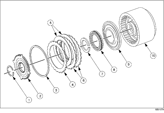
REVERSE CLUTCH REMOVAL/INSTALLATION


BUE051700000114

.

1
Retaining ring
2
Reverse clutch hub
3
Snap ring
4
Pressure plate
5
Drive plate
6
Driven plate
7
Retaining ring
8
Return spring component
9
Piston component
10
Drum component

Removal

1. Remove the reverse clutch pressure plate retainer snap ring.

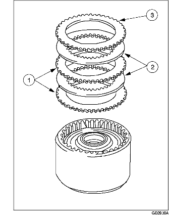
2. Remove the reverse clutch plates.

(1) Pressure plate
(2) Drive plate
(3) Driven plate
• Inspect for damage or wear.

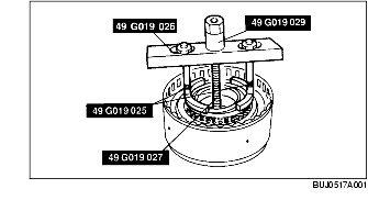
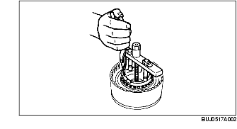
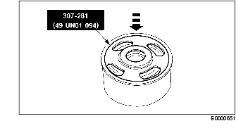
3. Using the SSTs, compress the reverse clutch return springs.

Warning
• Use caution when releasing tool pressure on the clutch piston springs. Failure to follow these instructions can result in personal injury.
Caution
• Do not compress the reverse clutch return springs completely.

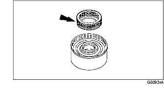
4. Remove the retaining ring.

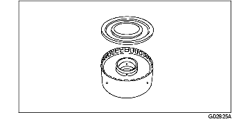
5. Remove the reverse clutch return spring component.

6. Remove the reverse clutch piston component.

7. Clean the clutch plates with a lint-free cloth.

Warning
• Air pressure must not exceed 138 kPa {1.4 kgf/cm2, 20 psi}. Wear safety glasses when using compressed air. Failure to follow these instructions can result in personal injury.
Note
• Do not clean the clutch plates in a vapor degreaser or with any other type of detergent solution. Clean all parts thoroughly in a clean solvent and blow dry with moisture-free regulated compressed air.

8. Inspect the parts for damage and wear:

• Clutch plates
• Piston and seals
• Bushing
• Check ball in drum
• Drum outer surface band contact area
• Piston bore

Installation

1. Before assembly, soak the internal spline clutch plates in clean ATF for 30 minutes or more.

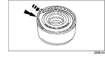
2. Using the SST, install the reverse clutch piston component.

3. Install the reverse clutch return spring component.

4. Using the SSTs, compress the reverse clutch return springs.

Warning
• Use caution when releasing tool pressure on the clutch piston springs. Failure to follow these instructions can result in personal injury.
Caution
• Do not compress the reverse clutch return springs completely.

5. Install the reverse clutch retaining ring.

6. Install the reverse clutch plates.

(1) Install the driven plates.
(2) Install the drive plates.
(3) Install the reverse clutch pressure plate.

7. Install the reverse clutch pressure plate retainer snap ring (selective fit).

8. Measure the clearance between the reverse clutch pressure plate and the reverse clutch pressure plate retainer snap ring with a feeler gauge.

• Take a second measurement on the opposite side.
• Average the two measurements to obtain the clearance.
• If the clearance is not within the specifications, select and install the correct thickness retaining ring to obtain the specified clearance.
• Retaining ring sizes:
• 1.39-1.49 mm {0.054-0.058 in}
• 1.53-1.63 mm {0.060-0.064 in}
• 1.68-1.78 mm {0.066-0.070 in}