AUTOMATIC TRANSAXLE ASSEMBLY
BUE051700000122
Preparation Before Assembly
1. Prepare the transaxle for assembly by performing the following procedures:
-
• Clean all parts (except the drive plates, seals, and intermediate/overdrive band) in solvent.
-
• Dry all parts with moisture-free regulated compressed air (do not use shop towels).
-
• Lubricate all internal parts (including drive plates) with clean ATF.
-
• Make sure the complete assortment of selective thickness parts are on hand for adjustments during assembly:
-
- Drive sprocket thrust washers.
-
- Driven sprocket thrust bearing shims.
-
- Differential case thrust bearing shims.
-
- Low/reverse clutch pressure plates.
-
• During assembly, use petroleum jelly to hold the parts in place (do not use grease).
-
• Lightly coat bolt and nut threads with ATF.
-
• Prepare the silicone sealant.
Assembly
1. Install intermediate and overdrive band component into the transaxle case.
2. Install the No.1 pump support thrust bearing.
-
• Lubricate the seal rings with clean ATF.
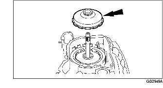
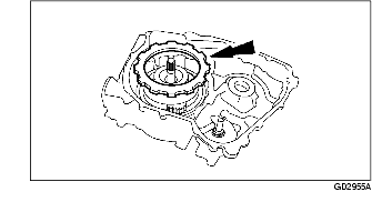
3. Install pump component into the case.
-
Note
-
• Apply a thin coat of petroleum jelly to the pump support seals and to the pump bore in the transaxle.
4. Tighten the bolts in the indicated sequence.
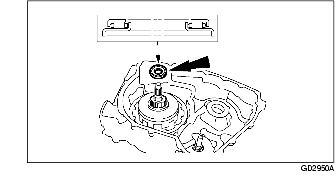
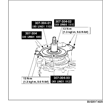
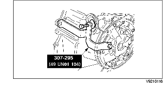
5. Using the SSTs, install the low/reverse clutch piston.
-
• Lubricate seals and piston bore with clean ATF.
6. Install the low/reverse clutch return spring component.
7. Install the low/reverse clutch return spring retaining ring.
8. Install the low/reverse clutch wave spring.
-
Caution
-
• The low/reverse clutch wave spring is fitted in this position for measurement purposes only.
9. Install the low/reverse clutch plates.
-
(1) Install the low/reverse clutch external spline driven plates.
-
(2) Install the low/reverse clutch internal spline drive plates.
-
(3) Install the low/reverse clutch pressure plate.
10. Install the low one-way clutch thrust plate.
-
Caution
-
• The low one-way clutch thrust plate is fitted in the position for measurement purposes only.
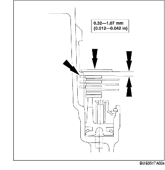
11. Measure the clearance between the low/reverse clutch pressure plate and the low one-way clutch thrust plate.
-
• Take a second measurement on the opposite side.
-
• Average the two measurements to get the clearance.
-
• If the clearance is not within specification, select and fit the correct thickness pressure plate to obtain the specified clearance.
-
• Pressure plate sizes:
-
• 2.06-2.16 mm {0.081-0.085 in}
-
• 2.26-2.36 mm {0.089-0.092 in}
-
• 2.46-2.57 mm {0.097-0.101 in}
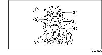
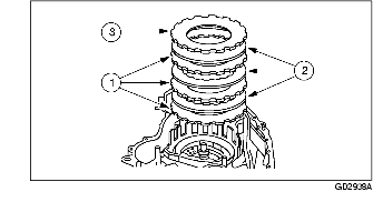
12. Remove the low one-way clutch thrust plate, the low/reverse clutch pressure plate, the low/reverse clutch external spline driven plates, the low/reverse clutch wave spring, and the low/reverse clutch internal spline drive plates.
-
Note
-
• One tooth of the low/reverse clutch pressure plate is notched for identification.
-
(1) Low one-way clutch thrust plate.
-
(2) Low/reverse clutch pressure plate.
-
(3) Low/reverse clutch external spline driven plates.
-
(4) Low/reverse clutch wave spring.
-
(5) Low/reverse clutch internal spline drive plates.
13. Install the No. 1 pump support thrust bearing component.
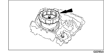
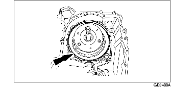
14. Install the forward/coast/direct clutch cylinder assembly and reverse clutch drum assembly.
-
Note
-
• Remove the seal sizer from forward/coast/direct clutch cylinder.
15. Install the turbine shaft.
16. Install the No. 4 turbine shaft thrust bearing.
17. Install the forward one-way clutch and low/intermediate sun gear component.
18. Install the No. 5 low/intermediate sun gear thrust bearing.
19. Install the low/intermediate carrier component.
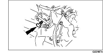
20. Install the No. 6 low/intermediate carrier thrust bearing.
21. Install the low/intermediate ring gear component.
22. Install the No. 7 reverse/overdrive sun gear thrust bearing.
23. Install the reverse/overdrive sun gear and shell component.
24. Install the reverse/overdrive carrier assembly together with the No. 8 thrust bearing.
25. Install the low/reverse clutch plates (model dependent).
-
(1) Install the low/reverse clutch external spline driven plates.
-
(2) Install the low/reverse clutch internal spline drive plates.
-
(3) Install the low/reverse clutch pressure plate previously selected.
26. Install the low/reverse clutch wave spring.
27. Install the low one-way clutch component with the identification ring on the inner ring facing upward.
28. Install the low one-way clutch thrust plate.
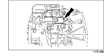
29. Install the low one-way clutch retaining ring.
-
Note
-
• Make sure to position the low one-way clutch retaining ring as shown.
30. Install the manual valve detent lever actuating rod component.
-
• Install the parking cam actuator lever.
31. Install the manual valve detent lever.
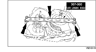
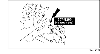
32. Install the SSTs.
33. Install the SST with short spacers.
34. Using the dial gauge, measure the distance from the top of SST to the No. 12 driven sprocket bearing surface area.
-
• Record this dimension.
-
• This dimension is designated with A.
35. Using the dial gauge, measure the distance from the top of the SST to the bearing surface on the reverse/overdrive carrier component on one side of the turbine shaft.
-
• Repeat this measurement on the other side of the turbine shaft 180 degrees from the first measurement.
-
• The average of these two dimensions is dimension B.
-
• Remove the SST.
36. Subtract dimension B from dimension A to obtain dimension C.
37. Use dimension C to select the correct No. 11 driven sprocket shim.
-
• Select a shim from the driven sprocket shim chart.
Driven Sprocket Alignment Shim No.11
|
Shim size
|
mm {in}
|
|
Transaxle case to driven sprocket/final drive sun gear thrust bearing shim AB:
|
2.10-2.20
{0.082-0.086}
|
|
Transaxle case to driven sprocket/final drive sun gear thrust bearing shim BB:
|
1.92-2.02
{0.075-0.079}
|
|
Transaxle case to driven sprocket/final drive sun gear thrust bearing shim CB:
|
1.75-1.85
{0.068-0.072}
|
|
Transaxle case to driven sprocket/final drive sun gear thrust bearing shim DB:
|
1.57-1.67
{0.061-0.065}
|
|
Transaxle case to driven sprocket/final drive sun gear thrust bearing shim EB:
|
1.40-1.50
{0.052-0.059}
|
|
Transaxle case to driven sprocket/final drive sun gear thrust bearing shim FB:
|
1.22-1.32
{0.048-0.051}
|
|
Select thrust bearing shim AB if measured distance C is:
|
14.1-14.34
{0.557-0.564}
|
|
Select thrust bearing shim BB if measured distance C is:
|
14.00-14.16
{0.551-0.557}
|
|
Select thrust bearing shim CB if measured distannce C is:
|
13.83-13.99
{0.544-0.551}
|
|
Select thrust bearing shim DB if measured distance C is:
|
13.66-13.82
{0.537-0.544}
|
|
Select thrust bearing shim EB if measured distance C is:
|
13.49-13.65
{0.531-0.537}
|
|
Select thrust bearing shim FB if measured distance C is:
|
13.32-13.48
{0.524-0.531}
|
38. Install and lubricate the following:
-
(1) Lubricate the needles and seals in the No. 18 driven sprocket bearing with ATF.
-
(2) Install the selected No. 11 driven sprocket shim.
-
(3) Install the No. 12 driven sprocket bearing.
39. Install the No. 9 reverse/overdrive ring gear thrust bearing.
40. Install the reverse/overdrive ring gear component.
-
Note
-
• Installation of the reverse/overdrive ring gear component at this time is for measurement purposes only.
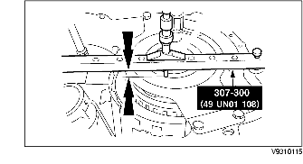
41. Install the SSTS.
42. Install the SST with short spacers.
43. Using the dial gauge, measure the distance from the top of the SST to the face of the reverse/overdrive ring gear component surface area.
-
• Repeat this measurement 180° from the first measurement.
-
• The average of these two dimensions is dimension A.
-
• Remove the SST.
44. Add 25.4 mm {1.0 in}(thickness of the SST) and thickness of short spacers.
-
• This is dimension B.
45. Subtract dimension A from dimension B.
-
• This is dimension C.
46. Select No. 10 thrust washer from the drive sprocket thrust washer chart.
-
• Use dimension C to select the No. 10 drive sprocket thrust washer.
Drive sprocket alignment No.10 thrust washer
|
No.10 thrust washer
|
mm {in}
|
|
Drive sprocket to converter housing thrust washer AA:
|
1.41-1.51
{0.052-0.059}
|
|
Drive sprocket to converter housing thrust washer BA:
|
1.67-1.77
{0.065-0.069}
|
|
Drive sprocket to converter housing thrust washer CA:
|
1.93-2.03
{0.075-0.079}
|
|
Drive sprocket to converter housing thrust washer DA:
|
2.19-2.29
{0.086-0.090}
|
|
Select thrust washer AA if measured distance C is:
|
0.86-1.12
{0.033-0.040}
|
|
Select thrust washer BA if measured distance C is:
|
0.60-0.85
{0.023-0.033}
|
|
Select thrust washer CA if measured distance C is:
|
0.34-0.59
{0.013-0.023}
|
|
Select thrust washer DA if measured distance C is:
|
0.08-0.33
{0.003-0.012}
|
47. Use petroleum jelly and install the selected No. 10 drive sprocket thrust washer on the torque converter housing.
48. Remove the reverse/overdrive ring gear component.
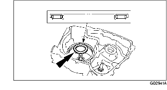
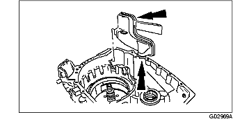
49. Install the filter and seal component.
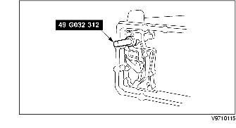
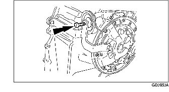
50. Install the SST in the filter eyelet and transaxle hole.
51. Using the SST, install the filter recirculating regulator exhaust seal.
-
Note
-
• Lubricate the filter recirculating regulator exhaust seal with ATF before installation.
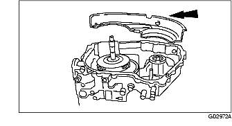
52. Install the chain pan in the transaxle case.
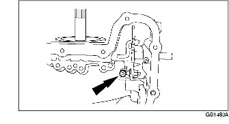
53. Assemble and install the drive chain component.
-
(1) Drive chain (copper colored link facing upward)
-
(2) Driven sprocket assembly
-
(3) Reverse/overdrive ring gear component
-
• Verify that the driven sprocket assembly and reverse/overdrive ring gear component are seated.
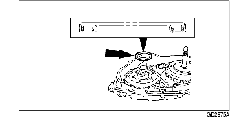
54. Install the chain pan cover by snapping it into place.
55. Install the No. 13 driven sprocket thrust bearing.
56. Install the final drive carrier and differential component.
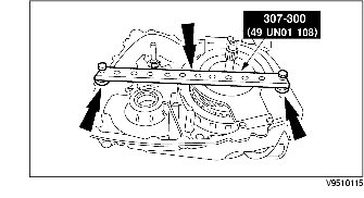
57. Install the SSTs and bolts.
-
Note
-
• Plastic washers should be placed between bolt heads and the SST.
58. Using the dial gauge, measure the distance from the top of the SST to the shim surface area of the final drive carrier and the differential component on one side of the hub.
-
• Repeat this measurement 180 degrees from the first measurement.
-
• The average of these two dimensions is dimension B.
59. Use combined thickness of the SST with long spacers 177.8 mm as dimension A.
60. Subtract dimension B from dimension A. This is dimension C.
61. Use dimension C to select the correct No. 14 differential bearing shim from the differential bearing shim chart.
Differential end play No.14 shim
|
Differential end play No.14 shim
|
mm {in}
|
|
Differential case to converter housing thrust bearing shim AA:
|
0.98-1.08
{0.038-0.042}
|
|
Differential case to converter housing thrust bearing shim BA:
|
1.28-1.38
{0.050-0.054}
|
|
Differential case to converter housing thrust bearing shim CA:
|
1.57-1.67
{0.061-0.065}
|
|
Differential case to converter housing thrust bearing shim DA:
|
1.87-1.97
{0.074-0.077}
|
|
Differential case to converter housing thrust bearing shim EA:
|
2.17-2.27
{0.085-0.089}
|
|
Select thrust bearing shim AA if measured distance C is:
|
130.46-130.76
{5.136-5.148}
|
|
Select thrust bearing shim BA if measured distance C is:
|
130.16-130.45
{5.124-5.135}
|
|
Select thrust bearing shim CA if measured distance C is:
|
129.87-130.15
{5.112-5.124}
|
|
Select thrust bearing shim DA if measured distance C is:
|
129.57-129.88
{5.101-5.112}
|
|
Select thrust bearing shim FA if measured distance C is:
|
129.27-129.56
{5.089-5.100}
|
62. Install the differential bearing component.
-
(1) Install the No. 14 differential bearing shim (selective fit).
-
(2) Install the No. 15 differential bearing.
63. Position the split flange gasket and install the torque converter housing onto the transaxle case.
-
Note
-
• Inspect the position of the valve tube on the converter housing.
64. Install the transaxle case bolts onto the torque converter housing in the indicated sequence.
65. Lubricate the assembly with clean ATF.
-
Note
-
• Note the number of grooves on the intermediate and overdrive servo apply rod.
-
(1) Install the intermediate and overdrive servo return spring assembly onto the servo piston assembly.
-
(2) Install the intermediate and overdrive servo apply rod and piston assembly.
-
(3) Install the overdrive servo apply rod spring.
66. Install the SST.
67. Assemble the SST.
-
Note
-
• Struts on the SST fit into the servo cover retaining ring groove.
-
(1) Install the struts.
-
(2) Install the bar.
-
(3) Install the bolts.
-
(4) Install the center bolt.
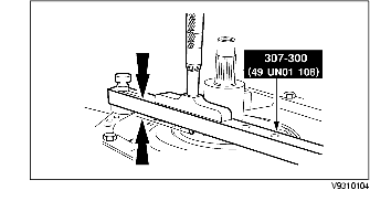
68. Using the dial gauge, measure the distance to the bar of the SST.
-
• Record this as dimension A.
69. Back off the center bolt of the SST until the piston movement stops.
70. Using the dial gauge, measure the dimension to the bar of the SST and record this as dimension B.
Vehicles with narrow groove case
Vehicles with wide groove case
-
• Subtract dimension A from B to find the travel.
-
• If the travel is not within the specification, select a new intermediate and overdrive servo apply rod component.
Intermediate/overdrive servo apply rod
|
Number of Rings
|
Rod Length
|
|
0
|
108.1 mm {4.25 in}
|
|
1
|
107.1 mm {4.21 in}
|
|
2
|
105.7 mm {4.16 in}
|
71. Wipe the servo piston and the servo cover cap with a lint-free cloth.
72. Inspect the servo piston for cracks on its pressure surfaces and in the sealing area. Inspect damage near the point where the servo piston is attached to the servo rod.
-
Caution
-
• Do not clean the rubber sealing surfaces of the servo piston and servo cover cap with cleaning solvent, or damage to the sealing surface may result.
73. Squeeze the servo piston lip for flexibility. If the lip feels brittle, install a new piston.
74. Inspect the servo retainer spring for cracks, breaks or deformation.
75. Assemble the SST.
-
Warning
-
• Servo return spring force is very high. Failure to follow these instructions can result in personal injury. Use caution when assembling.
76. Install the SST.
77. Tighten the SST bolt.
-
Caution
-
• If the case is stamped "WG'", install a wide-groove snap ring, or damage to the servo will result.
-
• Do not use a screwdriver to install the retaining ring or damage to the case may occur. Use only snap ring pliers to install the retaining ring.
-
Note
-
• If the servo cover will not seat deep enough in the bore to install the servo cover retaining ring, use a blunt punch or small hammer and gently tap the cover around the outer edge until the servo cover retaining ring can be installed.
-
• Install the servo cover retaining ring, using retaining ring pliers.
78. Loosen the SST bolt.
-
• When spring tension is released, remove the SST.
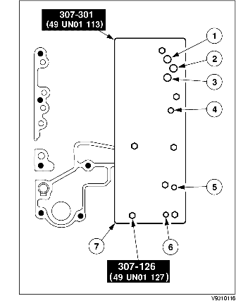
79. Using the SSTs, inspect the hydraulic circuits. Use a rubber-tipped blow gun and 19 kPa {0.19 kgf/cm2, 2.8 psi} of moisture-free regulated compressed air.
-
Caution
-
• Do not inspect the coast clutch since the piston may be forced out of the forward clutch piston.
-
Note
-
• If any leaks occur, make sure the SST is correctly seated.
-
(1) Reverse clutch test port
-
(2) Forward clutch test port
-
(3) Direct clutch test port
-
(4) Low/reverse clutch test port
-
(5) Servo release test port
-
(6) Servo apply test port
-
(7) Transaxle air test plate
-
• If air leakage is detected, disassemble the transaxle and locate source of leakage.
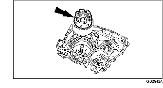
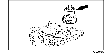
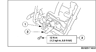
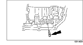
80. Install the thermostatic fluid level control valve.
-
(1) Position the thermostatic fluid level control valve.
-
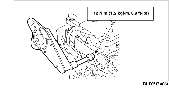
(2) Install the bracket.
-
(3) Install the thermostatic fluid level control valve bracket bolt.
81. Install forward clutch circuit filter (if equipped).
82. Install the solenoid body electrical connector O-ring seal and install the electrical connector into its bore in the transaxle case.
-
Caution
-
• Do not pull wires or damage the solenoid body electrical connector. Damage to the connector and terminals can result.
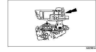
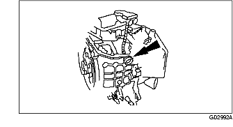
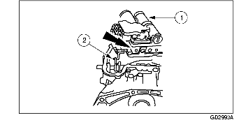
83. Connect the manual valve.
-
Caution
-
• Handle the main control valve body with care to prevent manual valve damage.
-
(1) Lift the main control away from the case.
-
(2) Connect the Z-link to the manual valve.
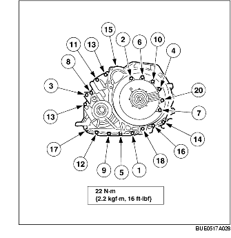
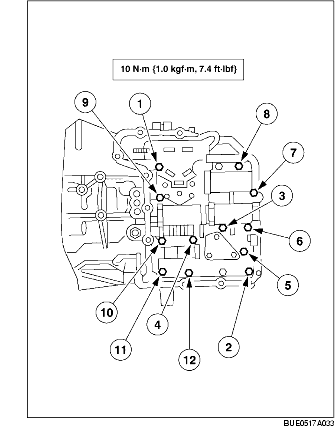
84. Install the main control valve body mounting bolts.
-
Note
-
• Tighten the bolts in sequence shown. Bolts 1, 7 and 9 are longer than the others.
85. Loosen the nut on the ball stud for the manual valve detent lever actuating rod component.
86. Move the manual control lever shaft to the "D" position.
-
• Install pin to hold the SST in place.
87. Move the manual valve detent lever component to the "D" position.
88. Tighten the nut on the ball.
-
• Remove the shifter pin from the SST.
89. Tighten the detent nut. Rotate back to "D" position to reinspect the adjustment.
90. Using the SST, reinspect the manual control lever assembly setting.
91. Install the manual control lever.
92. Rotate the manual valve detent lever assembly to the neutral position.
-
(1) 1 Range
-
(2) 2 Range
-
(3) D range
-
(4) N position
-
(5) R position
-
(6) P position
93. Position the TR switch.
94. Using the SST, align the TR switch and tighten the bolts.
95. Install the main control cover gasket.
96. Install the main control cover and tighten the bolts in the indicated sequence.
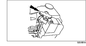
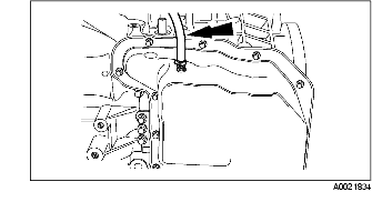
97. Install the vent tube.
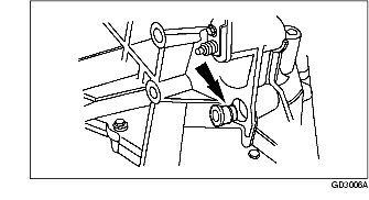
98. Install a new transaxle filler tube grommet.
99. Install the transaxle filler tube component.
-
(1) Install the tube.
-
(2) Install the transaxle filler tube bolt.
-
- Install the fluid level indicator.
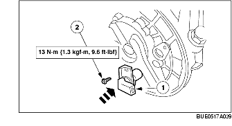
100. Install the turbine shaft speed (TSS) sensor.
-
(1) Use petroleum jelly on the O-ring seal and position the TSS sensor.
-
- Install a new O-ring seal.
-
(2) Install the TSS sensor bolt.
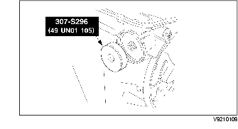
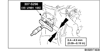
101. Using the SST, install the LH differential seal.
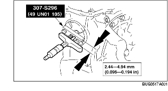
102. Using the SST, install the RH differential seal.
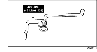
103. Using the SST, install the torque converter fluid seal.
-
Note
-
• Make sure the torque converter seal garter spring does not become dislodged during fitting. If the garter spring does become dislodged, install a new torque converter seal.
-
• Coat the torque converter seal garter spring with petroleum jelly.
104. Install the drain plug.
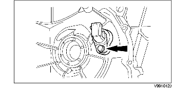
105. Install the output shaft speed (OSS) sensor.
106. Install the pump drive shaft.
-
Note
-
• Inspect correct rotation of the pump drive shaft.
107. Remove the transaxle from the SSTs.