.
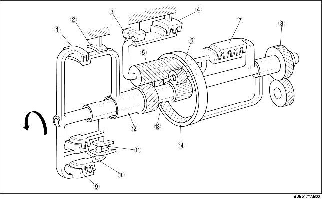
• When hydraulic pressure acts upon the clutch piston, the drive plates and the driven plates are pressed tightly together, and the rotation of the turbine shaft is transmitted via the reverse and forward drum and one-way clutch 1 to the small sun gear.
• When hydraulic pressure acts on the clutch piston, the drive plates and the driven plates are pressed tightly together, and the rotation of the turbine shaft is transmitted via the reverse and forward drum, coasting clutch drum and one-way clutch inner race to the small sun gear.
• Then when the coasting clutch engages, the forward clutch is engaged and the one-way clutch 1 becomes locked.
• The return spring is common for the forward clutch and the coasting clutch.

.
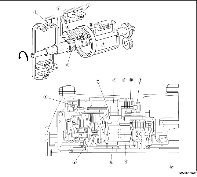
• When hydraulic pressure acts on the clutch piston, the drive plates and the driven plates are pressed tightly together, and the rotation of the turbine shaft is transmitted via the 3-4 clutch drum and the carrier hub to the planetary carrier.
• When hydraulic pressure acts on the clutch piston, the drive plates and the driven plates are pressed tightly together, and the rotation of the turbine shaft is transmitted via the reverse and forward drum and the 2-4 brake drum to the large sun gear. A diaphragm spring is used for return spring.

.
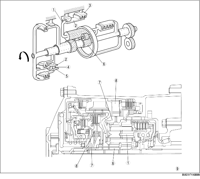
• When hydraulic pressure is applied between the servo retainer and the servo piston (brake band engagement side), the servo piston overcomes the spring force and acts on the brake band, thus locking the 2-4 brake drum.
• When hydraulic pressure is applied between the servo piston and the transaxle case (brake band disengagement side), the servo piston is pressed toward the servo retainer side. The brake band expands by its own spring force, thus releasing the 2-4 brake drum.
• When hydraulic pressure is applied simultaneously between the servo retainer and the servo piston and between the servo piston and transaxle case, the servo piston is pressed to the servo retainer side as a result of the difference of the surface area between the two, thus releasing the 2-4 brake drum.
• When hydraulic pressure acts on the brake piston, the drive plates and the driven plates are pressed tightly together, and the transaxle case and the low and reverse brake inner race are connected. The rotation of the planetary carrier is locked when the low and reverse brake is activated.
.
• If the rotation speed of the one-way clutch outer race is faster than that of the one-way clutch inner race, the sprags enter between the two races and lock them. Consequently, the driving force is transferred to the small sun gear via one-way clutch 1. In 4GR, the one-way clutch 1 runs idle and does not transfer the driving force because the rotation speed of the one-way clutch inner race is faster.
• The one-way clutch inner race rotates counterclockwise freely. However, in the roller type, if the inner race tries to rotate clockwise, the rollers move to the shallower grooves and enter between the races. In either case, the one-way clutch inner race is locked. In other words, one-way clutch 2 locks the clockwise rotation of the planetary carrier and the pinion gear.
.
|
1
|
Planetary carrier
|
|
2
|
Inner race
|
|
3
|
One-way clutch 2
|
|
4
|
One-way clutch 4
|
|
5
|
Outer race
|
|
6
|
Small sun gear
|
|
7
|
One-way clutch inner race
|
|
8
|
One-way clutch outer race
|
|
9
|
All rotations are viewed the oil pump
|