AUTOMATIC TRANSAXLE AND TRANSFER ASSEMBLY
BUE051700000A09
Precaution
General notes
1. Select the adjustment shims, referring to Bearing Preload.
2. If the drive plates or 2-4 brake band are replaced with new ones, soak the new part in ATF for at least two hours before installation.
3. Before assembly, apply ATF to all seal rings, rotating parts, O-rings, and sliding parts.
4. All O-rings, seals, and gaskets must be replaced with the new ones included in the overhaul kit.
5. Use petroleum jelly, not grease, when assembling again.
6. When it is necessary to replace a bushing, replace the subassembly that includes that bushing.
7. Assemble the housing within 10 minutes after applying sealant, and allow it to cure for at least 30 minutes after assembly before filling the transaxle with ATF.
-
Warning
-
• Although the stand has a self-locking brake system, there is a possibility that the brake may not hold when the transaxle is held in a lopsided position on the stand. This would cause the transaxle to turn suddenly, causing serious injury. Never keep the transaxle tilted to one side. Always hold the rotating handle firmly when turning the transaxle.
Assembly
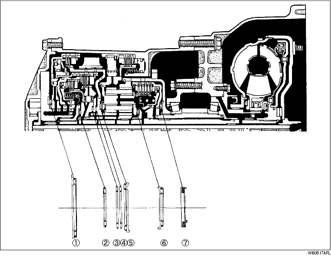
Bearing and race locations
-
Note
-
• The bearing and race at locations 2, 3, 4, 6, and 7 are one-piece units.
Outer diameter of bearing and race
|
|
1
|
2
|
3
|
4
|
5
|
6
|
7
|
|
Bearing (mm {in})
|
86.1 {3.39}
|
56.1 {2.21}
|
62.15 {2.447}
|
62.15 {2.45}
|
72.0 {2.83}
|
56.1 {2.21}
|
71.0 {2.80}
|
|
Race (mm {in})
|
88.0 {3.46}
|
-
|
-
|
-
|
72.0 {2.83}
|
57.0 {2.24}
|
72.0 {2.83}
|
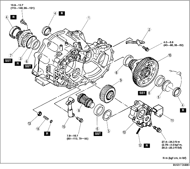
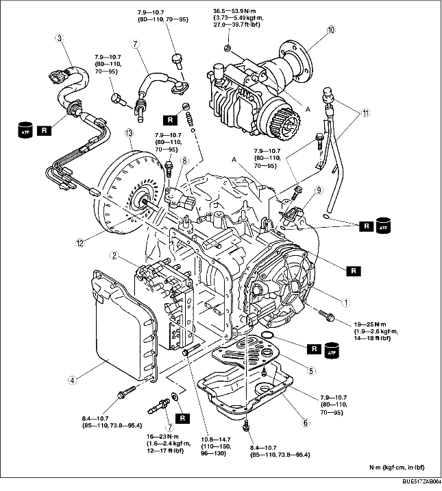
Components
.
|
1
|
Converter housing
|
|
2
|
Baffle plate
|
|
3
|
O-rings
|
|
4
|
Oil seals
|
|
5
|
Adjustment shim
|
|
6
|
Bearing races
|
|
7
|
Bearing cover component
|
|
8
|
Output gear
|
|
9
|
Idler gear
|
|
10
|
Bearing housing
|
|
11
|
Baffle plate
|
|
12
|
Roll pin
|
|
13
|
Orifice check valve
|
|
14
|
Orifice check spring
|
|
15
|
2-3 accumulator
|
|
16
|
Front differential
|
.
|
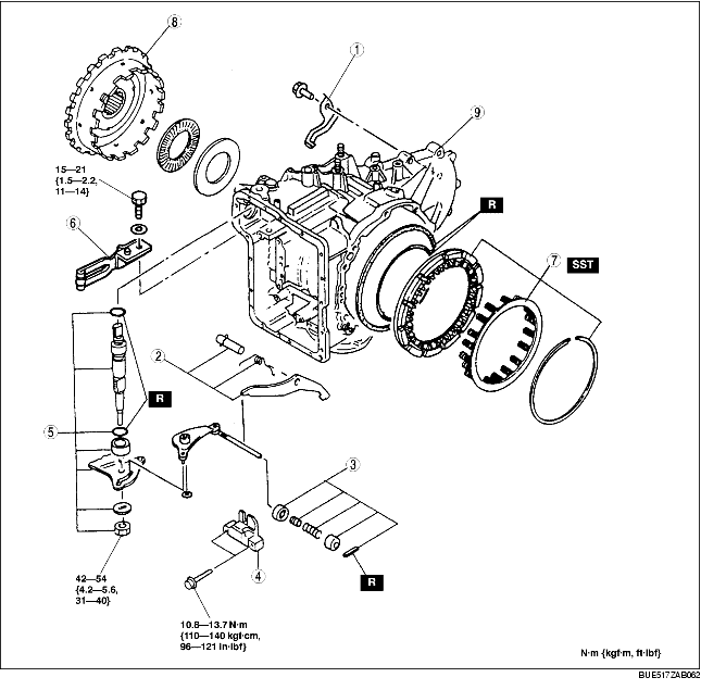
1
|
Baffle plate
|
|
2
|
Parking pawl
|
|
3
|
Parking assist lever
|
|
4
|
Actuator support
|
|
5
|
Manual shaft and manual plate
|
|
6
|
Detent spring
|
|
7
|
Low and reverse brake
|
|
8
|
Output shell
|
|
9
|
Transaxle case
|
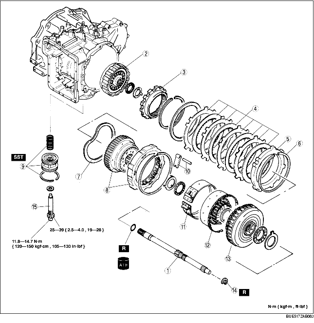
.
|
1
|
Turbine shaft
|
|
2
|
3-4 clutch
|
|
3
|
Internal gear
|
|
4
|
Low and reverse brake
|
|
5
|
Retaining plate
|
|
6
|
Snap ring
|
|
7
|
Friction plate
|
|
8
|
One-way clutch 2 and carrier hub component
|
|
9
|
Band servo
|
|
10
|
Anchor strut and shaft
|
|
11
|
2-4 brake band
|
|
12
|
Small sun gear and one-way clutch 1
|
|
13
|
Clutch component
|
|
14
|
Snap ring
|
|
15
|
Piston stem
|
.
|
1
|
Oil pump
|
|
2
|
Control valve body
|
|
3
|
Coupler component
|
|
4
|
Control valve body cover
|
|
5
|
Oil strainer
|
|
6
|
Oil pan
|
|
7
|
Oil pipe
|
|
8
|
TR switch
|
|
9
|
Input/turbine speed sensor
|
|
10
|
Transfer
|
|
11
|
Oil dipstick and oil filler tube
|
|
12
|
Oil pump shaft
|
|
13
|
Torque converter
|
Assembly procedure
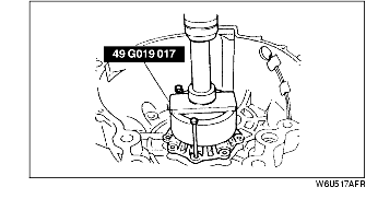
1. Align the bearing cover with guide bolts as shown and press it in. Install and tighten the mounting bolts.
-
Tightening torque
-
10.8-13.7 N·m {110-140 kgf·cm, 96-121 in·lbf}
2. Press the bearing race into the converter housing.
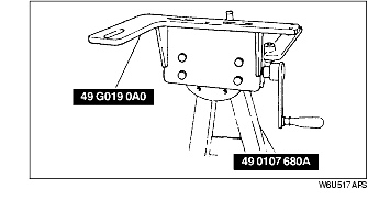
3. Assemble the SST.
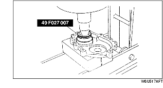
4. Install the idler gear and output gear by tapping in with a plastic hammer.
5. Install the selected shims and bearing race into the bearing housing using the SST.
6. Install the bearing housing.
-
(1) Install the bearing housing on the converter housing, and tighten the bolts evenly and gradually.
-
Tightening torque
-
27.4-34.3 N·m {2.79-3.5 kgf·m, 20.2-25.3 ft·lbf}
-
(2) Align the slot of the idler shaft with the mark on the bearing housing.
-
(3) Tap a new roll pin in using a pin punch and a hammer.
7. Install the 2-3 accumulator piston.
-
(1) Install the orifice check valve spring and orifice check valve.
-
(2) Apply ATF to new O-rings and install them into the 2-3 accumulator.
-
(3) Install the 2-3 accumulator piston.
-
Tightening torque
-
7.9-10.7 N·m {80-110 kgf·cm, 70-95 in·lbf}
8. Install the bearing race into the converter housing.
9. Install the baffle plate.
-
Tightening torque
-
4.0-5.8 N·m {40-60 kgf·cm, 35-52 in·lbf}
10. Install the front differential.
11. Install the selected shims and bearing race into the transaxle case.
12. Install the manual shaft and manual plate.
-
(1) Install the manual plate, spacer, washer, and nut.
-
(2) Tighten the nut to the specified torque.
-
Tightening torque
-
42-54 N·m {4.2-5.6 kgf·m, 31-40 ft·lbf}
-
(3) Install the detent spring.
-
Tightening torque
-
15-21 N·m {1.5-2.2 kgf·m, 11-15 ft·lbf}
-
(4) Move the manual shaft and verify that the parking pawl operates correctly.
13. Install the output shell to the output gear, and install the thrust bearing onto the output shell.
-
Thrust bearing outer diameter
-
71.0 mm {2.80 in}
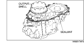
14. Apply a light coat of silicone sealant to the contact surfaces of the converter housing and the transaxle case.
15. Install new O-rings into the converter housing.
16. Install the transaxle case on the converter housing, and tighten the bolts evenly and gradually.
-
Tightening torque
-
38-51 N·m {3.8-5.3 kgf·cm, 28-38 in·lbf}
17. Install the SST into the differential side gears.
18. Install the turbine shaft and 3-4 clutch component.
-
(1) Assemble the turbine shaft and 3-4 clutch component.
-
(2) Verify that the thrust bearing and race are properly installed.
-
(3) Install the turbine shaft and 3-4 clutch component into the transaxle case.
19. Adjust the SST position so that it contacts and holds the turbine shaft.
20. Install the internal gear.
-
(1) Install the internal gear to the output shell.
-
(2) Install the snap ring.
21. Install the carrier hub component.
-
(1) Verify that the thrust bearing and bearing race are installed in the correct position.
-
(2) Hold the turbine shaft with one hand to prevent it from rotating.
-
(3) Install the carrier hub component into the 3-4 clutch drum by rotating it.
22. Install the friction plate.
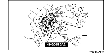
23. Install the one-way clutch 2.
-
(1) Hold the one-way clutch 2 horizontally.
-
(2) Install it by turning the carrier hub component counterclockwise.
-
(3) Install the snap ring.
24. Install the band servo to the transaxle case.
-
(1) Install the servo return spring and band servo.
-
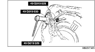
(2) Compress the servo using the SSTs.
-
(3) Install the snap ring.
-
(4) Remove the SSTs.
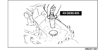
25. Install the piston stem.
26. Loosely tighten the piston stem by hand.
27. Install the anchor strut.
28. Install the 2-4 brake band in the transaxle case, and interlock it to the anchor as shown.
29. Install the small sun gear and one-way clutch 1.
-
(1) Verify that the thrust bearing and bearing race are installed in the correct position.
-
(2) Install the small sun gear and one-way clutch 1 component by rotating it.
30. Install the clutch component.
-
(1) Verify that the thrust bearing is installed in the correct position.
-
(2) Install the clutch component by rotating it.
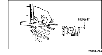
31. Measure the height difference between the reverse and forward drum and the transaxle case. If the height is not within specification, assemble again beginning with Step 21.
-
Height difference
-
0.7-1.9 mm {0.028-0.075 in}
32. Install the new snap ring into the bottom ring groove of the turbine shaft.
33. Use the following procedure to adjust the total end play and select a suitable bearing race.
-
(1) Set the thrust bearing onto the clutch component.
-
(2) Remove the bearing race and the oil pump gasket.
-
(3) Set the thickest bearing race (2.2 mm {0.084 in}) onto the oil pump.
-
(4) Set the oil pump onto the clutch component.
-
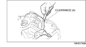
(5) Measure clearance A between the transaxle case and the oil pump. Take several measurements and calculate the average value.
-
(6) Select a suitable bearing race from the chart below.
|
Clearance A (mm {in})
|
Select this bearing race (mm {in})
|
|
0.91-1.10 {0.036-0.043}
|
1.2 {0.047}
|
|
0.71-0.90 {0.028-0.035}
|
1.4 {0.055}
|
|
0.51-0.70 {0.020-0.027}
|
1.6 {0.063}
|
|
0.31-0.50 {0.012-0.019}
|
1.8 {0.071}
|
|
0.11-0.30 {0.004-0.011}
|
2.0 {0.078}
|
|
0-0.10 {0-0.003}
|
2.2 {0.087}
|
-
(7) Remove the oil pump.
-
(8) Place the selected bearing race and a new gasket onto the oil pump.
-
(9) Install the oil pump onto the clutch component, and tighten the bolts evenly and gradually.
-
Tightening torque
-
19-25 N·m {1.9-2.6 kgf·m, 14-18 ft·lbf}
-
(10) Install the oil pipe.
34. Adjust the 2-4 brake band.
-
(1) Loosen the locknut and tighten the piston stem to the specified torque.
-
Tightening torque
-
11.8-14.7 N·m {120-150 kgf·cm, 105-130 in·lbf}
-
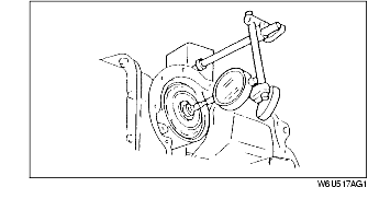
(2) Install a dial indicator and magnetic base to the oil pump. Set the dial indicator against the piston stem.
-
Warning
-
• Using compressed air can cause dirt and other particles to fly out, causing injury to the eyes. Wear protective eye wear whenever using compressed air.
-
(3) While keeping compressed air applied to the 2-4 brake band engagement passage, set the dial indicator to zero.
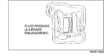
-
Air pressure
-
390-400 kPa {3.9-4.1 kgf/cm2, 56-58 psi}
-
(4) Stop applying compressed air, and verify the piston stroke by inspecting the dial gauge. Adjust the piston stem and apply compressed air repeatedly until the stroke is within specification.
-
Stroke
-
0.8-1.2 mm {0.0394-0.0472 in}
-
(5) Hold the piston stem and tighten the locknut to the specified torque.
-
Tightening torque
-
25-39 N·m {2.5-4.0 kgf·m, 19-28 ft·lbf}
35. Install a new O-ring and oil strainer to the transaxle.
-
Tightening torque
-
7.9-10.7 N·m {80-110 kgf·cm, 70-95 in·lbf}
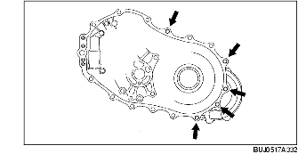
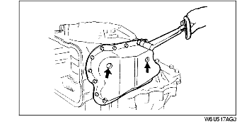
36. Install the magnets inside the oil pan in the positions shown in the figure.
37. Apply a light coat of silicone sealant to the contact surfaces of the transaxle case and the oil pan.
38. Install the oil pan to the transaxle case.
-
Tightening torque
-
8.4-10.7 N·m {85-110 kgf·cm, 73.8-95.4 in·lbf}
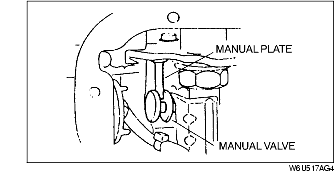
39. Align the manual valve with the pin on the manual plate.
40. Install the control valve body into the transaxle case, and tighten the bolts evenly and gradually.
-
Tightening torque
-
10.8-14.7 N·m {110-150 kgf·cm, 96-130 in·lbf}
41. Install a new O-ring to the coupler component.
42. Install the coupler component.
43. Match the harness coupler, and connect the solenoid connectors and TFT sensor connector.
44. Apply a light coat of silicone sealant to the contact surfaces of the transaxle case and control valve body cover.
45. Install a control valve body cover, and tighten the bolts evenly and gradually.
-
Tightening torque
-
8.4-10.7 N·m {85-110 kgf·cm, 73.8-95.4 in·lbf}
46. Install the steel ball, spring, packing, and oil pipe.
47. Install the bolt.
-
Tightening torque
-
7.9-10.7 N·m {80-110 kgf·cm, 70-95 in·lbf}
48. Install the input/turbine speed sensor.
-
Tightening torque
-
7.9-10.7 N·m {80-110 kgf·cm, 70-95 in·lbf}
49. Install the TR switch.
50. Adjust the TR switch.
-
(1) Connect an ohmmeter between the terminals A and H.
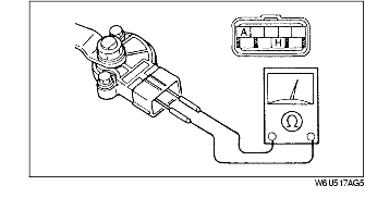
-
(2) Rotate the manual shaft fully counterclockwise, then return it two notches to the N position.
-
(3) Adjust the switch to the point where there is continuity between the terminals.
-
(4) Tighten the switch.
-
Tightening torque
-
7.9-10.7 N·m {80-110 kgf·cm, 70-95 in·lbf}
-
Note
-
• When it is necessary to install the manual shaft lever to the manual shaft, use an adjustable wrench to hold the manual shaft lever, then use a wrench other than an impact wrench to tighten the manual shaft nut to the specified torque
-
Caution
-
• Do not use an impact wrench or tighten the manual shaft nut without holding the manual shaft lever, as the transaxle may become damaged.
51. Tighten the manual shaft nut.
-
Tightening torque
-
32-46 N·m {3.2-4.7 kgf·m, 24-33 ft·lbf}
52. Remove the transaxle from the SST (transaxle hanger).
53. Install a new O-ring to the transfer.
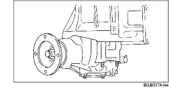
54. Install the transfer to the converter housing.
-
Tightening torque
-
36.5-53.9 N·m {3.73-5.49 kgf·m, 27.0-39.7 ft·lbf}
55. Install the oil dipstick and oil filler tube along with a new O-ring to the transaxle case.
-
Tightening torque
-
6.9-9.8 N·m {80-110 kgf·cm, 69.5-95.4 in·lbf}
56. Install the oil pump shaft.
57. Install a new O-ring onto the turbine shaft.
58. If the torque converter has been drained and washed, hold the torque converter in an upright position and fill it with new ATF.
-
ATF type
-
M-III or equivalent (e.g.DexronII)
59. Carefully install the converter to the torque converter housing. Rotate the torque converter to align the splines.
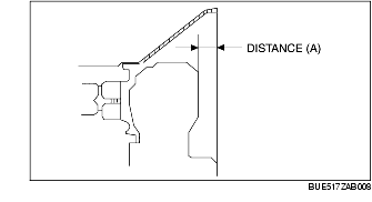
60. To ensure that the torque converter is installed accurately, measure distance A between the end of the torque converter and the face of the converter housing.
-
Distance A
-
13.96 mm {0.5496 in}