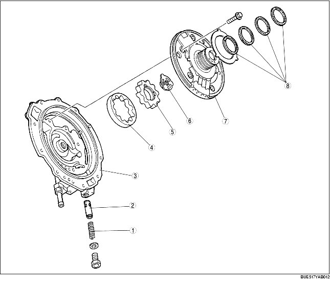
• An outer rotor, inner rotor, and oil pump flange are installed within the pump housing of the trochoid gear oil pump. The oil pump flange and oil pump shaft are coupled to the inner rotor.
• The other end of the oil pump shaft is coupled to the pump impeller side of the torque converter.
• As a result, the oil pump flange, the inner rotor, and the outer rotor rotate unitedly with the engine. A spool and spring installed in the discharge section of the pump housing regulates the oil discharge.
.
|
1
|
Spring
|
|
2
|
Spool
|
|
3
|
Oil pump housing
|
|
4
|
Outer rotor
|
|
5
|
Inner rotor
|
|
6
|
Oil pump flange
|
|
7
|
Oil pump cover
|
|
8
|
Seal ring
|
1. When the speed of the engine is low, the spool is as shown in Fig. A and the amount of oil discharged increases in proportion to engine speed.
2. When the engine speed increases and the P-P' differential pressure becomes greater, the spool is pressed against the spring and compresses it as it moves to the right. When the spool is in the position shown in Fig. B, the oil is redirected through port A to port B and circulates back to the inlet side of the pump, with the result that the amount of oil discharged is fixed.

.