1. Apply ATF to the inner and outer faces of the seals and install them to the reverse piston.
2. Face the outer seal lip toward the inside by gently rolling it down around the circumference for easier installation into the reverse and forward drum.
3. Install the reverse piston by pushing evenly around the circumference, being careful not to damage the seal rings.
4. Install the piston return spring with the tabs facing upward.
5. Install the return spring stopper with the step facing upward.
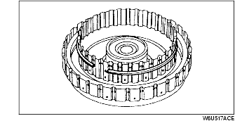
6. Install the snap ring half-way down the reverse and forward drum as shown.
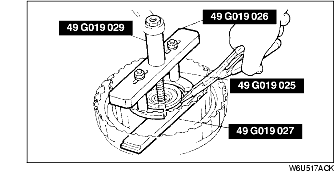
7. Install the SSTs on the reverse and forward drum.
8. Compress the piston return spring component.
9. Install the snap ring.
10. Remove the SSTs.
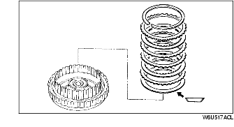
11. Install the drive and driven plates in the following order.
Driven-Drive-Driven-Drive
12. Install the retaining plate.
13. Install the snap ring.
14. Measure the reverse clutch clearance between the retaining plate and the drive plate.
Snap ring sizes
15. Apply ATF to the inner and outer faces of the seals, and install them onto the coasting clutch drum.
16. Face the outer seal lip toward the inside by gently rolling it down around the circumference for easier installation into the reverse and forward drum.
17. Install the reverse piston by pushing evenly around the circumference, being careful not to damage the seal rings.
18. Apply ATF to the inner and outer faces of the seals and install them onto the coasting clutch piston.
19. Face the outer seal lip toward the inside by gently rolling it down around the circumference for easier installation into the coasting clutch drum.
20. Install the coasting clutch piston by pushing evenly around the circumference, being careful not to damage the outer seal.
21. Install the spring and retainer component.
22. Install the SSTs in the coasting clutch.
23. Compress the spring and retainer.
24. Install the snap ring.
25. Remove the SST.
26. Install the dished plate with the dished side facing upward.
27. Install the drive and driven plates in the following order.
Driven-Drive-Driven-Driven-Drive
28. Install the retaining plate.
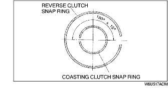
29. Install the coasting clutch snap ring in the direction shown in the figure.
30. Measure the clearance between the retaining plate and the snap ring. Make several measurements and calculate the average value.
Snap ring sizes
31. Install the dished plate with the dished side facing downward.
32. Install the drive and driven plates in the following order.
Driven-Drive-Driven- Drive-Driven-Drive
33. Install the retaining plate.
34. Install the forward clutch snap ring in the direction shown in the figure
35. Measure the clearance between the retaining plate and the snap ring. Make several measurements and calculate the average value.
Snap ring sizes
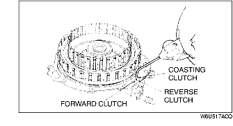
36. Set the clutch component onto the oil pump.
37. Inspect the clutch operation by applying compressed air through the fluid passages shown.
38. Apply petroleum jelly to the thrust bearings, and secure them onto reverse and forward drum.