1. Apply ATF to the new inner and outer seals, and install them onto the low and reverse brake piston.
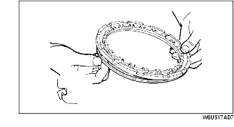
2. Face the outer seal lip toward the inside by gently rolling it down around the circumference for easier installation into the case.
3. Install the low and reverse brake piston by pushing evenly around the circumference, being careful not to damage the outer seal.
4. Install the spring and retainer component.
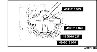
5. Install the SSTs in the transaxle case as shown.
6. Compress the spring and retainer.
7. Install the snap ring.
8. Remove the SSTs.
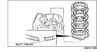
9. Install the wave spring with the buff finish downward.
10. Install the drive and driven plates in the following order.
Driven-Drive-Driven-Drive-Driven-Drive-Driven-Drive
11. Install the retaining plate.
12. Install the snap ring.
13. Measure the clearance between the low and reverse brake retaining plate and the snap ring. Make several measurements and calculate the average value.
Retaining plate sizes
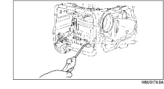
14. Inspect the low and reverse brake operation by applying compressed air through the fluid passage as shown in the figure.