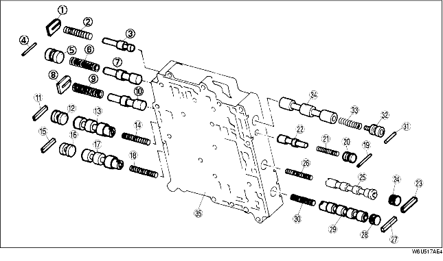
MAIN CONTROL VALVE BODY DISASSEMBLY
BUE051721100A18
-
Caution
-
• Denting or scratching these precisely machined components will reduce the ability or the transaxle to shift properly. When handling these components or the valve body that contains them, be careful not to drop or hit them.
-
• Using a magnet in this procedure could magnetize the valve body inner components, reducing the ability of the transaxle to shift properly. Do not use magnets or magnetized tools when carrying out maintenance on these components.
-
Note
-
• If a valve does not slide out under its weight, place the valve body open-side and tap on the valve body lightly with a plastic hammer.
1. Disassemble in the order indicated in the table.
-
Warning
-
• Using compressed air can cause dirt and other particles to fly out, causing injury to the eyes. Wear protective eye wear whenever using compressed air.
2. Clean all parts and holes using compressed air and apply ATF to them immediately before assembly.
.
|
1
|
Spring retainer
|
|
2
|
Converter relief spring
|
|
3
|
Converter relief valve
|
|
4
|
Stop pin
|
|
5
|
Stop plug
|
|
6
|
Solenoid reducing spring
|
|
7
|
Solenoid reducing valve
|
|
8
|
Spring retainer
|
|
9
|
Low reducing spring
|
|
10
|
Low reducing valve
|
|
11
|
Stop pin
|
|
12
|
Stop plug
|
|
13
|
1-2 shift valve
|
|
14
|
1-2 shift spring
|
|
15
|
Stop pin
|
|
16
|
Stop plug
|
|
17
|
2-3 shift valve
|
|
18
|
2-3 shift spring
|
|
19
|
Stop pin
|
|
20
|
Stop plug
|
|
21
|
Coast timing spring
|
|
22
|
Coast timing valve
|
|
23
|
Stop pin
|
|
24
|
Stop plug
|
|
25
|
TCC shift valve
|
|
26
|
TCC shift spring
|
|
27
|
Stop pin
|
|
28
|
Stop plug
|
|
29
|
3-4 shift valve
|
|
30
|
3-4 shift spring
|
|
31
|
Stop pin
|
|
32
|
Stop plug
|
|
33
|
Pressure modifier spring
|
|
34
|
Pressure modifier valve
|
|
35
|
Main control valve body
|