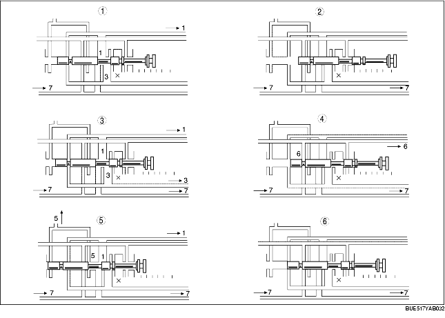
• When the selector lever is moved, the manual valve moves also, until it is located in a position where line pressure (7) is distributed to each line pressure circuit for P, R, and N positions and D, 2, and 1 ranges. Line pressures (1), (3), (5), and (6) are distributed to each valve. When line pressure (7) is not in a distribution position, the line pressures (1), (3), (5), and (6) are drained at the X position.
Line pressure (1)
• 1-2 shift valve
• 2-3 shift valve
• 3-4 shift valve
• N-D accumulator
• Forward clutch
• TCC control valve
Line pressure (3)
• 2-3 shift valve
Line pressure (5)
• Low reducing valve
Line pressure (6)
• 1-2 shift valve
• N-R accumulator
• Reverse clutch
• Low and reverse brake
.