TRANSFER ASSEMBLY
BUE051727500A05
Before Service Precautions
• Assemble with bare hand or using vinyl gloves. To prevent the foreign material from entering the transfer, do not use cotton work gloves or rag.
• Apply sufficient gear oil to the sliding surfaces and O-rings, and be careful not to damage when assembling.
• Replace the transfer with a new one if the case alignment surface is damaged. Be careful not to damage it since it may cause oil leakage.
• When installing silicone sealant, clean off the old sealant adhering to the sealing area and clean the sealing area with the cleaning fluids.
• After installing a seal, leave the parts alone for 2 h or more. Do not add oil or operate the vehicle during this time.
-
Warning
-
• The engine stand is equipped with a self-lock mechanism. However, if the transfer is tilted, the self-lock mechanism could become inoperative. This could cause the transfer to rotate accidentally, resulting in injury. Therefore, make sure that the transfer is not tilted when it is on the engine stand. When turning the transfer, grasp the rotation handle firmly.
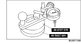
Assembly
|
1
|
Transfer carrier
|
|
2
|
Ring gear shaft
|
|
3
|
Ring gear
|
|
4
|
Bearing inner race (side)
|
|
5
|
Bearing outer race (front)
|
|
6
|
Bearing outer race (rear)
|
|
7
|
Spacer
|
|
8
|
Oil seal
|
|
9
|
Bearing
|
|
10
|
Clip
|
|
11
|
Spacer
|
|
12
|
Bearing inner race (front)
|
|
13
|
Distance piece
|
|
14
|
Bearing inner race (rear)
|
|
15
|
Drive pinion gear
|
|
16
|
Bearing outer race (side)
|
|
17
|
Ring gear component
|
|
18
|
Adjustment shim
|
|
19
|
Spacer
|
|
20
|
Bearing cap
|
|
21
|
Spacer
|
|
22
|
Idle gear
|
|
23
|
Oil seal
|
|
24
|
Companion flange
|
|
25
|
Washer
|
|
26
|
Locknut (companion flange)
|
|
27
|
Locknut (idle gear)
|
|
28
|
Rear cover
|
|
29
|
Side cover
|
Assembly Procedure
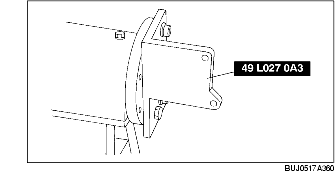
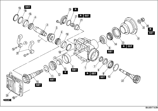
1. Assemble the SST.
2. Install the transfer to the SST.
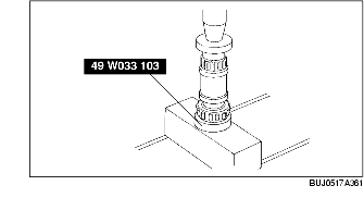
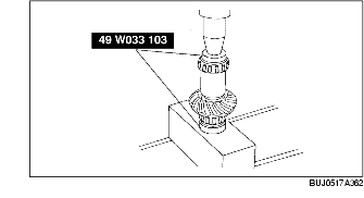
3. Using a press, assemble the locknut side bearing inner race (side) to the ring gear shaft.
4. Using a press assemble the ring gear to the ring gear shaft.
5. Using a press, assemble the ring gear side bearing inner race (side).
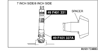
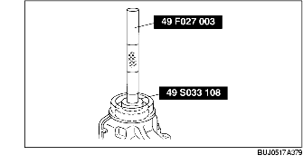
6. Using the SSTs, assemble the bearing outer race.
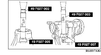
7. Using the SSTs, adjust the drive pinion height as follows:
-
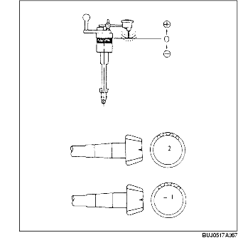
(1) Install the SSTs to the removed spacer and bearing.
-
(2) Assemble the spacer, bearing and SSTs. Using an O-ring, secure the SST.
-
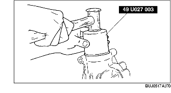
(3) Assemble the bearing, SSTs, companion flange, washer, and nut.
-
(4) Tighten the nut to the companion flange to where it can still be rotated by hand.
-
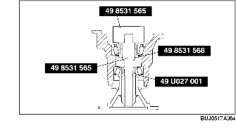
(5) Place the SSTs on the plate surface and set the dial gauge to "0".
-
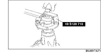
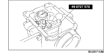
(6) Position the SST (49 0727 570) on the driver pinion model.
-
(7) Attach the dial gauge head to where the carrier bearing outer race (side) is installed and measure lowest position. Also, measure the value of where the side bearing outer race (side) is installed on the opposite side.
-
(8) Add the values for the both sides measured in Step 7 and divide by 2. From this value, subtract the value listed on the drive pinion end (if not written, it is "0") divided by 100, and then add 1.47. This is the pinion height adjustment value.
-
Note
-
• If the value measured in Step 7 and 8 is -1.47 mm {-0.0579 in} and 1.45 mm {0.0571 in}, and the drive pinion end value is 2, the formula would be (-1.47)+ (-1.45)/2-2/100+1.47=-0.01. Therefore, a spacer 0.01 mm {0.0004 in} thinner than the old one would be used. Since spacer thickness varies by 0.015 mm {0.0020 in}, select the spacer nearest the required size and assemble.
|
Identification mark
|
Thickness (mm {in})
|
Identification mark
|
Thickness (mm {in})
|
|
08
|
3.08 {0.1213}
|
09
|
3.095 {0.1219}
|
|
11
|
3.11 {0.1224}
|
12
|
3.125 {0.1230}
|
|
14
|
3.14 {0.1236}
|
15
|
3.155 {0.1242}
|
|
17
|
3.17 {0.1248}
|
18
|
3.185 {0.1254}
|
|
20
|
3.20 {0.1260}
|
21
|
3.215 {0.1266}
|
|
23
|
3.23 {0.1272}
|
24
|
3.245 {0.1278}
|
|
26
|
3.26 {0.1283}
|
27
|
3.275 {0.1289}
|
|
29
|
3.29 {0.1295}
|
30
|
3.305 {0.1301}
|
|
32
|
3.32 {0.1307}
|
33
|
3.335 {0.1313}
|
|
35
|
3.35 {0.1319}
|
36
|
3.365 {0.1325}
|
|
38
|
3.38 {0.1331}
|
39
|
3.395 {0.1335}
|
|
41
|
3.41 {0.1343}
|
42
|
3.425 {0.1348}
|
|
44
|
3.44 {0.1354}
|
45
|
3.455 {0.1360}
|
|
47
|
3.47 {0.1366}
|
-
|
-
|
8. Assemble the spacer selected for pinion height adjustment with the round off side facing the gears.
9. Using the SST, assemble the bearing inner race (front) to the drive pinion gear.
10. Assemble a new distance piece to the drive pinion gear.
11. Assemble the drive pinion to the transfer carrier.
12. Install the bearing inner race (rear), companion flange, washer, and new locknut to the drive pinion and temporarily tighten.
13. Rotate the companion flange by hand and to seat the bearing.
14. Using the SST, tighten the locknut from the lower limit of the specified tightening torque and set to the preload value. Note the tightening torque when the specified preload value is obtained.
-
Tightening torque
-
127-284 N·m {13.0-29.0 kgf·m, 95-209 ft·lbf}
-
Drive pinion preload value
-
0.88-1.37 N·m {9.0-14.0 kgf·cm, 7.9-12.1 in·lbf}
15. Remove the locknut, washer, and companion flange.
16. Apply oil to the lip area of a new oil seal.
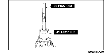
17. Using the SST, assemble the oil seal.
18. Apply the grease to the bearing contact surface of the companion flange.
19. Assemble the companion flange.
20. Using the SST, tighten the new locknut to the tightening torque noted when preload was adjusted.
21. Reverify the preload.
-
Preload value
-
0.88-1.37 N·m {9.0-14.0 kgf·cm, 7.9-12.1 in·lbf}
22. Install the spacer to the bearing outer race (side) locknut side installation area.
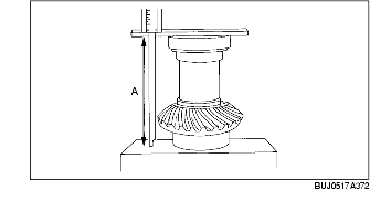
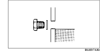
23. Place the side bearing race and on top of ring gear on the surface plate as shown in the figure, and measure the height using a vernier caliper and straight edge. This is dimension A.
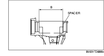
24. Measure the width of the transfer carrier ring gear installation area with the spacer installed. This is dimension B.
25. Total thickness C of the adjustment shims on both sides can be expressed by the following formula:
-
C1=B-A+0.096
-
C2=B-A+0.28
26. If the total thickness of the installed adjustment shims is between C1-C2, use the shims as they are.
27. If the total thickness of the installed adjustment shims is not between C1-C2, select two appropriate adjustment shims from the table below and use them.
|
Identification mark
|
Thickness (mm {in})
|
Identification mark
|
Thickness (mm {in})
|
|
350
|
3.50 {0.1378}
|
355
|
3.55 {0.1398}
|
|
360
|
3.60 {0.1417}
|
365
|
3.65 {0.1437}
|
|
370
|
3.70 {0.1457}
|
375
|
3.75 {0.1476}
|
|
380
|
3.80 {0.1496}
|
385
|
3.85 {0.1516}
|
|
390
|
3.90 {0.1535}
|
395
|
3.95 {0.1555}
|
|
400
|
4.00 {0.1574}
|
405
|
4.05 {0.1594}
|
|
410
|
4.10 {0.1614}
|
415
|
4.15 {0.1634}
|
|
420
|
4.20 {0.1654}
|
425
|
4.25 {0.1673}
|
|
430
|
4.30 {0.1693}
|
435
|
4.35 {0.1713}
|
|
440
|
4.40 {0.1732}
|
445
|
4.45 {0.1752}
|
|
450
|
4.50 {0.1772}
|
455
|
4.55 {0.1791}
|
|
460
|
4.60 {0.1811}
|
-
|
-
|
-
Note
-
• When reusing adjustment shims, do not mix up the right one and left.
-
• Do not mix up the right and left side bearing race and spacer.
28. Install the adjustment shim chose for the transfer carrier ring gear side and spacer on opposite side.
29. Assemble the ring gear and bearing race to the transfer carrier.
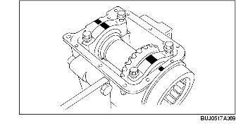
30. Using the SST, assemble the selected adjustment shim in between the spacer and bearing race as shown in the figure.
31. Align the alignment mark of the bearing cap, assemble the bearing cap, and tighten the bolt temporarily.
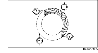
32. Set the dial gauge with the measuring probe attached perpendicularly to the end of one of the ring gear teeth.
33. Secure the drive pinion and measure the backlash from when the ring gear is moved.
-
Standard
-
Backlash: 0.09-0.11 mm {0.0035-0.0043 in}
-
Caution
-
• Perform the backlash measurement on the ring gear circumference at four points.
34. If the backlash is not within the specified range above, adjust it by sliding the ring gear in the shaft direction.
-
Note
-
• Slide the ring gear in the shaft direction by replacing the adjustment shim. If the right side adjustment shim is replaced with one that is 0.05 mm {0.002 in} thicker, the left side shim must be replaced with one that is 0.05 mm {0.002 in} thinner.
35. Align the bearing cap alignment mark and assemble the bearing cap.
-
Tightening torque
-
17.6-26.5 N·m {1.80-2.70 kgf·m, 13.1-19.5 ft·lbf}
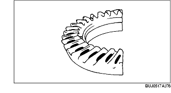
36. Perform the drive pinion and ring gear tooth contact inspection.
-
(1) Apply tooth marking compound evenly to both surfaces of the ring gear.
-
(2) Rotate the ring gear back and forth several times.
-
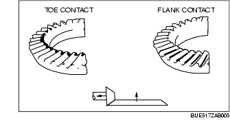
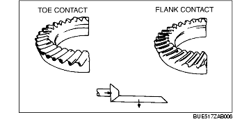
(3) Inspect for gear tooth contact at four points on the ring gear circumference and verify that the gear tooth contact indicated by tooth marking compound is as indicated in the figure.
-
• If the tooth contact points are normal, wipe off the marking compound.
-
• If the tooth contact points are not normal, adjust the pinion height, then adjust the backlash.
-
(4) If toe and flank contact is indicated as shown in the figure, replace the drive pinion spacer with a thinner one to maintain the drive pinion further away.
-
(5) If heal and face contact is indicated as shown in the figure, replace the drive pinion spacer with a thicker one to bring the drive pinion closer.
37. Assemble the idle gear side spacer.
38. Using the SSTs, assemble the oil seal.
39. Using the SSTs, assemble the bearing.
40. Assemble the clip.
41. Align the idle gear and ring gear shaft serrations and tap the idle gear lightly to assemble.
42. Assemble the locknut side spacer.
43. Assemble a new locknut.
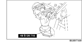
44. Using the SST, secure the companion flange and tighten the locknut to the specified tightening torque.
-
Tightening torque
-
127-206 N·m {13.0-21.0 kgf·m, 95-151 ft·lbf}
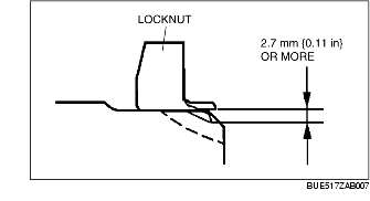
45. Crimp the locknut using a chisel and hammer.
-
Crimp size
-
2.7 mm {0.11 in} or more
46. Remove the transfer from the SST.
47. Apply oil to a new O-ring and assemble the side cover.
48. Assemble the side cover to the transfer.
-
Tightening torque
-
6.9-9.8 N·m {70-100 kgf·cm, 61-86 in·lbf}
-
Note
-
• Before applying silicone sealant, completely clean off any old silicone sealant and remove any oil or grease.
-
• After applying silicone sealant, install the rear cover within 10 min.
-
• After connecting the sealing area, leave it for 30 min or more, then add transfer oil.
49. Clean the alignment surface of the rear cover and transfer, and lightly apply silicone sealant.
50. Assemble the rear cover.
-
Tightening torque
-
6.9-9.8 N·m {70-100 kgf·cm, 61-86 in·lbf}
51. Remove the oil level plug and washer.
52. Position the transfer on level ground.
53. Add the specified oil through the oil level plug hole until it reaches the oil level plug hole filling port.
-
Specified oil
-
API Service GL-5 (SAE 80W-90)
-
Oil capacity (approx. quantity)
-
0.35 L {0.37 US qt, 0.31 lmp qt}