|
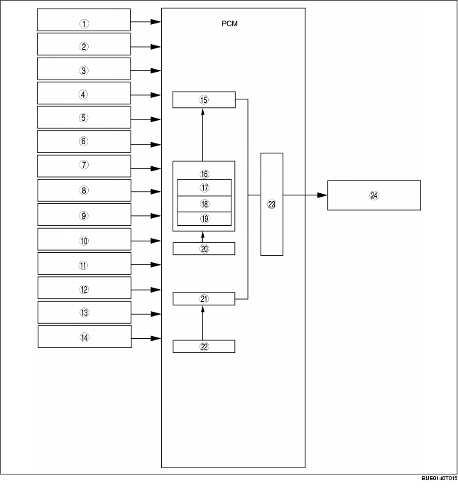
1
|
MAF/IAT sensor
|
|
2
|
TP sensor
|
|
3
|
MAP sensor
|
|
4
|
CMP sensor
|
|
5
|
CKP sensor
|
|
6
|
ECT sensor
|
|
7
|
HO2S
|
|
8
|
PSP switch
|
|
9
|
Vehicle speed signal (CAN)
|
|
10
|
TR switch
|
|
11
|
Brake switch
|
|
12
|
A/C switch
|
|
13
|
Refrigerant pressure switch
|
|
14
|
Battery voltage
|
|
15
|
Synchronized fuel injection
|
|
16
|
Effective injection time
|
|
17
|
Injection time at engine start
|
|
18
|
Basic injection time
|
|
19
|
Various correction types
|
|
20
|
Ineffective injection time
|
|
21
|
Non-synchronized injection control
|
|
22
|
Ineffective injection time
|
|
23
|
Fuel injector energization timing and energization time
|
|
24
|
Fuel injector
|